Turn on the light with your voice. "Alice, turn on the light." Voice control for smart home based on openHAB. Without programming and SMS. Setting up smart lamps from Xiaomi
Let's consider several experimental schemes that implement voice control of the load. The frequency filters are based on the LMC567CN chip. The choice of this particular microcircuit is due to its efficiency, since it is assumed that the microcircuit can be used in devices with transformerless power supply, for example, with a quenching ballast capacitor. If there are no restrictions on power efficiency, then a bipolar functional analogue can be used - a microcircuit of the LM567 type (domestic clone - KR1001XA01). The figure shows a circuit that decodes the frequency of the vowel sound “(Y”E)” in the command word “LIGHT”:
In this and the following circuits, the microphone amplifier is implemented on an operational amplifier DA1 of the KR140UD1208 type. A feature of the microcircuit is the ability to set the current consumption by a resistor (in the diagram - R5) connected to the 8DA1 output, which allows you to use the circuit in an economical mode. The gain sets the resistor R4 connected between the pins 2DA1 and 6DA1. This resistor sets the sensitivity of the circuit to voice commands. Resistors R2 and R3 form the virtual power supply midpoint DA1, setting the non-inverting input 3DA1 to about half the supply voltage. From the 6DA1 output, the amplified signal through the isolating C3 and the limiting current R6 is fed to the AC voltage level limiter - two counter-parallel germanium diodes VD1 and VD2. Diodes limit the signal at ~300…400mV peak-to-peak. Through R7 and separating C6, a limited signal is fed to the 3DA2 input. Resistors R9, R10 and capacitor C7 set the reference oscillator frequency (VCO center frequency). Resistor R10 is used to achieve a low level at the 8DA2 output when the “LIGHT” command is pronounced. At the drain of transistor VT1 (common connection point of resistors R11, R12 and diode VD3) the signal is inverted - log.1 appears. Trigger DD1.1 operates in single vibrator mode, the time constant of which is set by the elements R13 and C9. With the specified elements, the time is approximately one minute.
As a rule, sound interference is random and short-lived. The integrating circuit R12-C8 is necessary to suppress these interferences. When decoding the "LIGHT" command or the sound of interference, a low level appears at the 8DA2 output and VT1 closes. Through R11 and R12, C8 begins to charge. The charge time of C8 is longer than the duration of the interference, therefore, the vowel “E” in the word “LIGHT” should be pronounced a little longer than usual - light-E-Et. When the interference stops, then C8, charged to a certain voltage level, is quickly discharged through VD3 and the open drain-source channel of transistor VT1. This is the easiest way to cut off sound interference with the same frequency as the sound of the "E" vowel. The command sounds longer than the interference, so C8 will charge up to the switching threshold of the trigger DD1.1 at the input "S". The trigger will switch to a "single" state - on the main output log.1, and on the inverse - log.0. Through the open VD4, the capacitor C8 will quickly discharge, and C9 will start charging through R13. Depending on the logic of the actuator, the control signal can be removed from the outputs 1DD1.1 or 2DD1.1. If a command is received again during the operation of the executive device, then this will not change anything, because. C8 is shunted with a low voltage level from 2DD1.1 through an open diode VD4. In about a minute, the voltage at C9 will reach the trigger switching threshold at the input "R", the trigger will return to its original "zero" state and C9 will quickly discharge through the open VD5. The load will be de-energized. For verification, the device was assembled on a factory perforated board. Instead of the KP501A (VT1) transistor, a “telephone” current key of the KR1014KT1V type was installed:

A video demonstrating the operation of the circuit in FIG. 1 is shown below. The account imitates sound interference, while it is clear that the blue LED installed in the drain circuit of the transistor VT1 goes out, but the lamp does not turn on - the duration of the interference is short. The duration of the "LIGHT" command is longer - the lamp turns on. The "LAMP" or "ON" commands do not turn on the lamp:
Video 1
The second video demonstrates the operation of the device that responds to the "LIGHT ON" command with automatic load shutdown. The circuit of the device has not changed - the same as in FIG. 1, but the reference oscillator DA2 is tuned to the frequency of the “AND” sound with a tuning resistor R10. In addition, the value of the resistor R4 in the circuit feedback DA1 is increased to 5.1 megaohms, which determined the sensitivity of the amplifying path - the command is given from a distance of five meters from the microphone. Here, too, the score imitates sound interference. It is interesting to note that the device does not respond to the “POWER ON” command, although the “AND” vowel sound coincides in duration with the “AND” vowel in the “BURN” command. It can be assumed that the sound "I" after the consonant sound "Ch" in the command "TURN ON" has a higher frequency compared to the sound "I" after the consonant sound "R" in the command "BURN ON":
Video 2

Suppose, when power is applied, the trigger DD1.1 is set to a state in which the output 2DD1.1 is log.1, and the output 1DD1.1 is log.0. Diode VD5 is closed, and VD6 is open and shunts capacitor C8. The frequency of the reference oscillator DA1 with a tuning resistor R4 is tuned to the frequency of the sound “(Y”E)” in the command word “LIGHT”. When pronouncing the command and decoding, the transistor VT1 will close, so C7 will start charging. When the voltage reaches the switching threshold DD1.1 at the input "S", the trigger will switch to a "single" state, in which the output 2DD1.1 is log.0, and the output 1DD1.1 is log.1. Log.1 will go to the gate VT2 and open it. An open channel drain / source VT2 will connect the capacitor C6 in parallel with the capacitor C5 - the frequency of the reference oscillator will decrease. The device will be ready to accept the STOP command. Since the VCO frequency has changed, the low level at the 8DA1 pin will change to high and VT1 will open. Now C7 is shunted through the open diode VD5, and VD6 is closed, therefore, if you say the STOP command to turn off the load, C8 will be charged, which will lead to the next switching of the trigger DD1.1. In this circuit, as well as in the circuit in Figure 1, the elements R7, C7, VD3 and R8, C8, VD4 are designed to cut off sound interference, the frequencies of which coincide with the frequencies of vowels in command words. Diodes VD5 and VD6 provide the correct operation algorithm, determining the order in which capacitors C7 and C8 are charged. The capacitances of capacitors C5 and C6 may differ from those indicated in the diagram. First, by installing the capacitor C5 and adjusting R4, they achieve a reaction to the “LIGHT” command, then they select the capacitance C6, connecting it in parallel to the capacitor C5, so that there is a reaction to the “STOP” command. Only after that C6 is included in the drain circuit of the transistor VT2. FIG. 3 shows a diagram that implements the control of an incandescent lamp by the commands "ON" and "STOP":

In fact, the circuit is the same as the circuit in Figure 2, but with some differences. Analog keys are used as switching elements. The K561KT3 (or K1561KT3) chip contains four such keys. In the initial state, the DD1.2 key is open, because at the output 2DD2.1 - log.1, and the key DD1.3 is closed, since the output 1DD2.1 is log.0 and the incandescent lamp EL1 is off. open channel X-Y key DD1.2 tuning resistor R12 is shunted, thereby excluded from the reference oscillator circuit, so the VCO frequency is determined by the elements R10, R14, C7 and is tuned (by resistor R14) to the frequency of the “AND” sound in the command word “GORI”. When the command is decoded, the DD2.1 trigger switches, so the DD1.2 key closes and the DD1.3 key opens. The LED in the solid state relay VS1 turns on and the lamp EL1 lights up. Since the DD1.2 key is now closed, the tuning resistor R12 is connected in series with the resistors R10 and R14, which means that the VCO frequency becomes lower. With resistor R12, it is tuned to the frequency of the sound "O" in the "STOP" command. Resistors R8 and R9 set the hysteresis of the switching characteristics of the 8DA2 output, which contributes to more accurate command processing. Key DD1.1 works as an inverter. The HL1 LED goes out during signal decoding. This circuit was also tested on a breadboard and showed positive result works:

The demo video shows the operation of the device, assembled according to the scheme in Figure 3. As in the previous videos, the score imitates sound interference, other commands are given with different vowel durations:
Video 3
Figure 4 shows a variant of the circuit that accepts a command word with three vowels. As an example, the "SYSTEM" command is selected. Such a command can be used to launch a certain electronic unit or serve as a sound "key" to activate the circuit with other voice commands. Any other command word can be used, for example, "BATHROOM" to control the light in the bathroom or toilet rooms of the apartment:

The elimination of sound interference occurs differently than in the previous schemes - due to the sequential switching of triggers, and the next trigger fixes the state of the previous one. If an audio interference appears at the input, then in order to affect the state of the load, the frequency of the interference must change two times and coincide with the frequencies of the vowels in the command word in the desired sequence, and this seems to be very unlikely. In this circuit, the original VCO frequency is switched twice, so the DA2 tone decoder operates with three reference frequencies. In the initial state, the key DD1.2 is open and the frequency is determined by the elements C7, R11 and R12. With a trimmer R12, it is tuned to the sound "AND". After the “I” sound in the “SI” syllable is pronounced and decoded, the DD1.2 key will close and the DD1.3 key will open. Now the VCO frequency is set by the elements C7, R11 and R15, which adjust the device’s response to the sound “(Y”E)” in the syllable “CTE”. After decoding the sound “(Y”E)”, the DD1.3 key will close, but the DD1.4 key will open, which means that the frequency of the reference oscillator will be determined by the elements C7, R11 and R18, which adjust the VCO frequency to the sound “A” in the syllable “MA ". After the pronunciation and decoding of the sound "A", the DD1.4 key closes and the DA2 decoder stops working - its reference oscillator is turned off, because. all keys are closed. The circuit will return to its original state by the RESET signal, which it will receive from the actuator after the execution of the following commands or the completion of the operating cycle of the control object.
If an interference corresponding to the sound “AND” appears at the input, then the DD2.1 trigger will switch - the DD1.2 key will close, and the DD1.3 key will open. Now the frequency of the interference should coincide with the frequency of the sound “(Y”E)”. Miracles do happen in our lives, but very rarely. Therefore, after a time T = 0.7 * C8 * R13, the trigger DD2.1 will return to its original state, since it works in the single vibrator mode.
If there was a command and the sound “I” was followed by the sound “(Y”E)” (the syllables SI-STE were pronounced), then through the open diode VD5 the switched state of the trigger DD2.1 will be fixed - the capacitor C8 will not be able to charge up to the trigger switching threshold according to input "R". The same thing will happen with the DD2.2 trigger, if the sound “A” is decoded after the sound “(Y”E)” (all three syllables SI-STE-MA will be pronounced) - its switched state will be fixed by the open diode VD7. Each main output of the previous trigger is connected to the data input (D) of the next, so decoding the entire command word will only be possible if the vowels follow each other in a strict (correct) sequence. The LEDs connected to the circuit through current amplifiers VT1 - VT3 indicate the decoding of vowels. When the last sound is decoded, LED "A" remains on until the circuit receives a RESET signal from the actuator. When a RESET signal is received, the LEDs will switch in reverse order (from "A" to "I"), indicating the return of the device (trigger cells) to its original state. On the basis of this circuit, the circuit with the command word "TURN ON" and automatic load disconnection has been practically tested, shown below:

The circuit decodes vowel sounds (Y”U) and “I”. Connection from pin 4DD2.1 to pin 12DD2.2 through VD5, marked in red, to demonstrate the sequence of trigger cells. If this connection is removed, then the DD2.1 one-shot will return to its original state after a time of T = 0.8 seconds, regardless of whether the vowel “AND” is decoded or not. The signal after decoding is not fed through the inverter to the clock inputs “C” of the triggers from the 8DA2 output, therefore the sound (Y”U) is not limited in time. Only after it ends, the DD2.1 trigger will switch - a high voltage level will be applied to the clock input. The duration of the sound "I" is limited by the time T = 0.8 sec. The R13-C9 chain delays the appearance of a high voltage level at the 9DD2.2 input relative to its appearance at the 11DD2.2 input.
The video below shows the operation of the circuit in FIG. 5. It can be seen from the video that after decoding the sound (Y”U), the blue LED turns on, indicating the switching of the first trigger cell, and the incandescent lamp turns on only after the sound “I” is decoded, i.e. after switching the second trigger cell, which sets the load operation time using the elements R15 and C10. The return to the initial state occurs in the reverse order: the lamp turns off - the DD2.2 single vibrator has switched to its original state, and only then the LED goes out - the DD2.1 single vibrator has switched to its original state. Giving other commands does not turn on the incandescent lamp:
Video 4
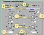
In the devices in the last two figures, commands are given in the usual way without stretching the vowels in syllables. And at the end of the topic, for example, I will give one more experimental circuit. This circuit as a "single" device was not tested, but its individual nodes were previously assembled and showed a positive result in work. The circuit allows you to turn on, turn off and adjust the brightness of an incandescent lamp with your voice, that is, this device is a voice dimmer. The circuit is shown in Figure 6:

The control part consists of two voice channels, the operation of which is described in the diagrams in FIG. 1 and FIG. 2. The first voice channel (DA2 and DD1.1) decodes the "LIGHT" command and controls the on or off of the EL1 lamp. The second voice channel (DA3 and DD1.2) decodes two commands - "START" and "STOP", controlling dimming. The VS1 triac is controlled by a DA5 chip of the K145AP2 type in a typical inclusion. The microcircuit has two control inputs - inverse 3DA5 and non-inverse 4DA5. The functional purpose of these inputs is the same - the first short signal will open the triac and the lamp will turn on, the second short signal will close the triac and the lamp will turn off. If the control signal is applied for a long time, then the microcircuit generates pulses that smoothly unlock or lock the triac. This causes the brightness of the lamp to change. If you turn off and then turn on the lamp, the brightness of the lamp will be the same as before turning it off. The logic of operation of these inputs is different - the 3DA5 input is controlled by a low logic level, and the 4DA5 input is controlled by a high one. When decoding the "LIGHT" command, the DD1.1 trigger will generate a short pulse with a low voltage level, which turns on the lamp. When decoding the "START" command, the DD1.2 trigger is set to a "single" state, so a high voltage level will be applied to the 4DA5 input and the brightness of the lamp will begin to change smoothly. If up to this point the brightness has decreased, now it will increase. If before that the brightness increased, now it will begin to decrease. If you do not give the STOP command for a long time, then the lamp brightness will change from minimum to maximum (or from maximum to minimum) and vice versa. After the "STOP" command is given and its decoding, the DD1.2 trigger will return to its original "zero" state and the regulation will stop - the lamp brightness will be fixed at the selected level. By submitting the “LIGHT” command again, you can turn off the lamp - at the 3DA5 input, the DD1.1 trigger will again generate a short pulse with a low logic level. The device is powered through a quenching capacitor C22 and a half-wave diode-zener diode rectifier VD9-VD10. Capacitor C18 smooths out ripples. microphone amplifier DA1 and tone decoders DA2, DA3 are powered by +5V from the linear regulator DA4. Transistors VT1 and VT2 not only act as signal inverters, but also match the logic levels of decoders and triggers. In the above experimental schemes, an incandescent lamp is used as a load, but various other control objects can be used. It all depends on the invention and scope of these schemes. For example, you can tune the tone decoder to the frequency of the vowels "A" and "Y", and connect the switching element to the "TALK" button circuit of the talking clock. Then, on the command "CLOCK", the clock will prompt the current time. And in the third, final part, I will introduce you to another, practical scheme.
Turning on and off the light, just giving him instructions with his voice ... A dream that is not possible to come true? Not at all! This is a completely accessible reality that the Smart Home system allows you to use in everyday life. Users have this opportunity smart home long ago.

However, today it is considered much more common and convenient to control the light using scripts that work more accurately than voice control. But if you are interested to know what the voice control system was, we will tell you a little more about it.
Varieties of systems and their features
So, about everything consistently and in detail. The first kind of intelligent voice light control - dimmers. Their working principle is quite simple and clear. They act in the same way as a switch on a relay, but the conductivity electric current controlled by sound signals. For example, you can set up such equipment to increase the sound intensity.
But this kind of voice switch has a quite obvious drawback: it can react not only to an increase in the volume of your voice, but also to other extraneous noises that reach the key it is programmed for. However, a smart manufacturer of this type of systems found a way out of the situation by proposing an option tone response.
Setting process
- First of all, you need to provide smart light sound sample to which it should respond.
- The second thing to do when setting up the system, assign sound signal a certain action.
Of course, the process of setting up such a lighting control is quite specific, but this is offset by its functionality, as well as the possibility of installation. This kind of equipment can be either completely hidden from prying eyes, or made in the form of a conventional switch.
Option for wall lighting fixtures
But this simple and quite budget option for voice control of lighting is limited in terms of functionality by what is applicable only for lighting equipment tied to a socket. That is, with its help it is impossible to control lamps and chandeliers that are installed on the ceiling.
But for bedrooms and children's rooms, in which floor lamps and bedside lamps are installed, for example, for reading, this kind of system is quite applicable and convenient.
Back to innovation
As you can see, in addition to the advantages, voice switches also have a number of disadvantages, therefore it is much more rational and competent to use scenarios formulated for your needs and functioning almost error-free in the light switching system for a smart home.
- tutorial
November 2017, the calendar displayed the number eleven. Sale on Aliexpress was in full swing, hands itched to buy something. The choice fell on " Mi-light RGBW led lamp AC86-265V Remote Control Smart Lighting". As a result, two copies were purchased maximum power, 9 watts, and a MiLight WiFi iBox hub controller. Delivery from China was not long in coming, and 4 months later, on March 13, 2018, (a platform that allows third-party developers to add skills to the Alice voice assistant). Next, Alice will learn how to control the lighting (and not only) in your apartment, and we will help her with this, step by step and without a single line of code.
1. Setting up smart lamps from Xiaomi.
The first thing to do is to set up the lamp control, at least with the help of the Xiaomi application. If this stage has been passed for you, feel free to proceed further, to setting up a smart home server, or even further, directly to the integration of Alice and openHAB. But first things first. The lamps themselves to your home router will not connect, this requires an iBox hub that can control up to four groups of light sources. You need to connect it to the network, and then associate the lamps with it.- We supply food to iBox by connecting it via usb, for example, to charger for phone.
- When connecting for the first time, you need to reset the hub settings, so click RST.
- Next, install the application on the phone from Xiaomi for iOS or Android. Make sure the phone is connected to home network WiFi.
- Opening the application Mi Light 3.0, press + . Here we are interested in the tab Smart Link.
- Enter your home name and password WiFi networks to which the phone is connected and will be connected iBox.
- Now you have iBox must be connected to the network, and the indicators SYS and LINK should blink, slowly and quickly respectively. If it's not, click RST again.
- If the lights are flashing, tap in the app Start Configuration, the connection setup process for the hub will begin.
- After ten seconds, the flashing will stop, then SYS starts blinking slowly again, and LINK will remain burning. The app will display a message Configured. The hub is connected to the network. If in the list device list it's not there, just click Searching for device.
- Open in app Mi Light 3.0 from the hub list Mi Light. We go to the section colors.
- At the top of the screen, select one of the zones, let it be Zone1. And click on the device linking icon in the upper right corner. The screen will open LINK/UNLINK with instructions.
- Now we set up those lamps that we want to bind to Zone1, they will be controlled synchronously in the future. To control the brightness and color of each lamp separately, they must be assigned to separate zones. So, turn on the lamp, and during the first three seconds, press in the application Link. If the lamp blinks three times, then everything is fine, the synchronization was successful. You can control the lamp.

In principle, at this stage you already have a remote for remote control light. Moreover, you can write your own lighting control system, since the protocol for communicating with the hub has long been known (once it was available at the link limitlessled.com/dev). There are ready-made libraries for php, javascript, python. But this control is possible only from local network, which is clearly not enough for Alice. Let's try to solve this problem.
2. Install openHAB
Briefly, what is openHab. This is a management server. smart home open source code. Developed by the community, supports the management of a huge number of devices. There is a mobile client, it is possible to control Alexa from Amazon and an assistant from Google. Written in java, based on the Eclipse SmartHome framework. So it can be installed even on a refrigerator, the main thing is that it works on this refrigerator virtual machine Java. Installation instructions are available for Linux , Windows , Mac OS , Raspberry Pi , various Synology NAS and QNAP . Let's quickly go over the first option.- Add repository keys:
Wget -qO - "https://bintray.com/user/downloadSubjectPublicKey?username=openhab" | sudo apt-key add - sudo apt-get install apt-transport-https
- Adding the repository itself:
echo "deb https://dl.bintray.com/openhab/apt-repo2 stable main" | sudo tee /etc/apt/sources.list.d/openhab2.list
- We update and install the server along with the additions:
sudo apt-get update sudo apt-get install openhab2 sudo apt-get install openhab2-addons sudo apt-get install openhab2-addons-legacy
- Setting up automatic start service after rebooting the device and run it:
sudo systemctl start openhab2.service sudo systemctl status openhab2.service sudo systemctl daemon-reload sudo systemctl enable openhab2.service
- Now we are waiting in the area 15-20 minutes(this is not an exaggeration, this is a harsh reality with jokes about the speed of Java), until it loads and a web interface appears at http://openhab-device:8080.
- On this page we are interested in the item Paper UI. It is with this type of interface that we will work in the future.

3. Light control via openHAB
So, we have a working smart home server and Xiaomi lamps with remote control. They need to be connected. openHAB supports bindings (instructions that allow you to control connected electronics) for many devices, including these lamps.
4. External access to openHAB
For security reasons, after the manipulations described above, the management of the smart home server is possible only from the local network. This is clearly not enough for our task. There are several configuration options: set up a VPN to access the local network from the Internet, configure a reverse proxy, or connect your server to the myopenHAB Cloud service at myopenHAB.org. Since in Russia the number of employees of Roskomnadzor is directly proportional to the number VPN users and proxy servers, we will use the last option.Existing should not be multiplied unnecessarily
- We register on the myopenHAB website, log in and go to https://myopenhab.org/account . On this page, we are interested in two fields: openHAB UUID and openHAB Secret. They allow you to organize the connection of servers. Let's see where to get them.
- We go to the control panel PaperUI openHAB.
- Opening the section Configuration → Add-ons → misc.
- Install openHAB Cloud Connector.
- AT Configuration → Services the module should appear openHAB Cloud with mode " Notifications & Remote Access".
- AT Configuration → System → Add-on Management switch must be activated Access Remote Repository".
- After installing the addon, the data we are looking for will be in the files /var/lib/openhab2/uid and /var/lib/openhab2/openhabcloud/secret (userdata/uuid and userdata/openhabcloud/secret, if not installed from the package). We enter them in the account settings on myopenHAB and click update. If everything is configured correctly, then the word " online". This indicates that access to your smart home from the Internet is open, but immediately Alice cannot use them. First you need to make the previously configured device available from the outside.
- Go to the section Configuration → Services → openHAB Cloud → Configure.
- Listed Items to expose to apps like IFTTT activate the checkbox for the brightness control and click Save.
- After a while, we check that the selected item is present in the list on the myopenhab.org/items page with the status " ON".

Now the lamp can be controlled from the Internet, via the openHAB Cloud API, which supports OAuth2 authorization. But, unfortunately, clients are predetermined, this is Alexa, Google Assistant and the IFTTT service. alice in this list not yet. But it's not a problem!
5. IFTTT
If this then then.
A service that allows you to build a chain of actions from several services. Conditionally respond with an action in one service if a trigger fired on an event in another service. IFTTT supports a huge number of services, including myopenHAB, which we are interested in. But does not support Alice. In general, anyone can create a module for their service there, first of all, for this you need to contact the sales department and find out the amount of your annual payment in favor of IFTTT. Our goal is to use the service for free in order to be able to redirect requests from Alice to openHAB.
- Register on the site ifttt.com and go to Applets → New Applet.
- After pressing + this, you need to select a service, the event in which will be a trigger. Because service alice is not on the list, we need to choose something that can receive commands from her. This is a service Webhooks. Click Connect.
- Next, select from the list with one item trigger " receiving a web request".
- Specify the name of the event, for example light_on, and press Create.
- Now you need to select a response action, click on + that. Our choice openHAB, connect.
- In the window that opens, mentioned earlier OAuth2 authorization, click on allow.
- Only reaction available send command".
- From the drop-down list, select the lamp control element (for example, Light_Switcher), and as the command to turn on the light, specify the word " ON". Create.
- Searching on the site IFTTT service Webhooks and go to the related documentation.
- On the page that opens, there is a command that we need to execute by replacing (event) on the light_on.
- After clicking on Test It, your lamp should turn on.

6. Alice
At my command, at my will, Alice will turn on the light if you use the Yandex.Dialogues platform. The platform opened in March of this year and allows anyone who wants to add skills to Alice by writing the appropriate code. On the this moment The catalog already contains a huge number of skills. Skill development is a topic for a separate article on Habré, and here we have " without a single line of code". So let's use the existing developments.- Installing, only it currently has support custom skills.
- We speak Alice "turn on magic spells". Precisely skill magic spells/magic spell will allow us to make POST requests to servers IFTTT.
- Click Add and specify the address to turn on the light of the form:
https://maker.ifttt.com/trigger/light_on/with/key/(user_id)
- The next step is to pronounce a phrase or word that Alice will respond to by executing a request at the specified address (my Alice responds to “turn on the light”).

You have to understand that it is not enough just to turn on Alice and say " turn on the lights". Yandex knows nothing about our smart home commands, data about them is stored in the skill database " magic spells". Therefore, you must first call the skill by saying " turn on magic spells", and only then turn the light on and off with your voice.
P.S.
The Alice and openHAB integration approach via IFTTT does not limit your imagination in any way. You can use the skill " magic spells"voice control any things in your smart home. For example, openHAB has a binding for Samsung SmartTV that allows you to control the sound and channels of the TV. The interaction between Alice and Webhooks is the implementation of a voice interface to all IFTTT services, " magic spells" allow you to execute a command of any of them. Or you can not use Alice at all, and write your own frontend, for example mobile app, which will make requests to IFTTT through all the same Webhooks. Yes, and IFTTT is not necessary to use, by analogy, you can configure " magic spells Add tagsVoice control is exactly the kind of feature we've all seen in the movies. A man enters the house, greets his invisible assistant and gives him all sorts of commands. The well-known Jarvis from Iron Man, well, who does not dream of such an assistant?
So far, voice control has not reached such a level as science fiction writers describe it, but it is steadily gaining momentum.
Light control is the first thing that comes to mind when you think of voice control. Lighting control is the most frequently used function, just go into the room and say "Turn on the backlight" and at that moment your invisible assistant will turn on the backlight, so you can start any element of the MiMiSmart smart home.
You don't need to take out your phone and launch the app. It is enough just to say - "start the script" Movie "" and at that moment the curtains will fall, the lights will turn off and the movie will start. Like in the movies, right?
Also, voice control is often used when you leave home or come home. "I have come" or "I have gone" is the most commonly used voice script. You left home, and your invisible assistant will turn off the lights, socket groups and arm your house. And when you come home after a long tiring day, say, "I'm here," and the house will turn on pleasant relaxing music for you, reduce the brightness of the lighting.
Voice commands can be anything from specific items such as "Turn on the TV", "Turn off the floor lamp", or "Turn off the music" to commands programmed into scripts. For example, “I left”, “Disco scenario”, “Turn on the Cinema”, “Turn on the heating”, in which not one action is performed, but a series of actions in order to achieve a specific goal.
Control can be done from the phone or through a microphone in the room. Moreover, global brands do not stand still and constantly release voice assistants, such as Google Home, Apple HomeKit or Amazon Echo.
The Smart Home system itself implies remote control almost all available devices and devices.
Moreover, the execution of commands is not limited to the “on / off” or “open / close” functions.
For media devices, the “quieter / louder” functions should still work, for lighting - “brighter / darker”.
All these commands can be given from a smartphone, but voice control of light, music, heating, and the front door is much more convenient.
Why is it necessary to control the "Smart Home" by voice
"Smart home" is not just an expensive toy. "Smart Home" is a hardware and software complex of various devices and devices that make the home safe, comfortable, and convenient for living.
All these devices are controlled by various remote controls, which manufacturers supply with almost all of their products.
As a result, several remote controls appear in the house, and its inhabitants need to remember the algorithms for working with equipment.
The supply of control signals to the "Smart Home" from a smartphone has its drawbacks. Firstly, the gadget must be constantly carried with you from room to room.
Secondly, its battery may be discharged, the smartphone itself may be lost, fall into the hands of intruders. Therefore, the optimal solution for the "Smart Home" is a voice control device. This device will save the inhabitants of the house from the need to keep a remote control in each room, remember different operation algorithms.
Such control in the "Smart Home" system leads to the uselessness of different-sized remote control units working for different "entry points".
Homemade voice control lighting system
Do-it-yourself voice control of lighting is not an easy task. To solve it, one desire is not enough.
It is necessary to carefully consider the scheme, calculate electrical parameters, select components, decide which software will be used, whether its modification is required, what may come from existing developments, what can be modified. It is desirable to be able to work with a soldering iron, with fine electronics.

But to make the voice control of the light yourself according to the principle of "On / Off." - it's just to make a spectacular toy. After all, if you make it so that the voice can only be controlled by turning on or off a single lighting device or a group of devices, then why can't the same function be extended to other devices?
To get a complete system open for expansion, called "Smart Home".
Ready-made modules for working with voice
Any similar system starts with the voice recognition module. The first acoustic signal recognition structures responded to pops: one pop - “turn on”, two pops - “turn off”.
Modern voice recognition structures are complex hardware and software devices capable of distinguishing hundreds of command messages given by voice, moreover, voices can be of different timbre, different volume, spoken words can have synonyms.

The most accessible modules for homemade products:
- Voice Recognition Module V3.1 (FZ0475) ;
- Robotech SRL EasyVR Shield0;
- Voice Recognition Module LD3320;
Each of these modules has its own advantages and disadvantages. Elechouse Voice Recognition Module V3.1 is designed to work with the Arduino kit.
Robotech SRL EasyVR Shield 5.0 has three work algorithms - precise, phonetic and tone. Voice Recognition Module LD3320 can edit keywords.
The simplest voice light switch
First, you should decide on the scheme and configuration of the voice light switch.
In the simplest case, such a device will include:
- voice recognition module;
- amplifier;
- controller;
- microphone;
- control relay (the number depends on how many lighting fixtures will be connected to the switch);
- five volt power supply;
- circuit components - LEDs, resistors, capacitors, triacs, mounting sockets, etc.
The amplifier is necessary so that the device can perceive spoken words from anywhere in the room, and not just near the microphone.

The controller is assembled on the basis of the Atmega8 microcontroller, which has its own random and permanent memory.
Triacs are used, firstly, as power switches, and, secondly, as dimmers that control the brightness of lighting. Information exchange protocol - UART.
How the voice switch works
The operation algorithm of such a switch is as follows. After the initial switching on, it is necessary to pause for several seconds in order for the voice recognition module itself to load and all devices of the device to be initiated. Then you need to install protection against unauthorized activation.
After all, anyone can say, for example, “turn on the light”, and the device will react accordingly. The same applies to a signal that is opposite in meaning.
Therefore, you need to set an initialization combination, for which you should pronounce a conditional word, some name. When this word is spoken, the signal LED will light up, confirming that the device is ready for operation.

Then any command can follow: “Turn on the chandelier”, “Turn on the floor lamp”, “Turn on the night light”. These signals must be programmed during instrument setup. Commands are recognized by the module and transmitted to the controller.
The controller, in turn, processes the information and generates a control signal for the relay, including the specified device. By the command "Turn off the chandelier", "Turn off the floor lamp", "Turn off the night light", the controller gives a control signal to turn off.
Inclusion of voice control of light in the "Smart Home" system
For the system to work, sensitive microphones must be placed in each room. Through the speech recognition module, commands will be sent to the controller.

Previously, the controller through the computer must be programmed for certain commands. Then from anywhere in the house it will be possible to voice control any device in any room, and, if necessary, in the yard.
Conclusion
There are developments for smartphones that allow you to control the voice of the Smart Home system.
For these developments, special peripherals with access codes are produced.
For a home-made system assembled on the basis of "Arduino" there are no such restrictions.
You can make and connect any devices to the Smart Home, not just lighting.
Video: Lutron voice control, Alexa