A simple high-quality headphone amplifier. Hu is a headphone amplifier. Making a housing for an amplifier
A headphone amplifier circuit that definitely deserves attention. There is double the output current and the absence of coupling capacitors in the signal path. At the same time, the headphone amplifier circuit is very simple and understandable.
Updated : The input decoupling capacitor has been removed from the circuit. The values of the input resistors have been changed.
Headphone amplifier circuit
Regular wanderings across endless expanses garbage dumps a storehouse of knowledge - the Internet, led to an interesting find. It was PDF file from Burr Brown. Which inspired me to create an op amp headphone amplifier. From the language of a potential enemy, its name can be literally translated as follows: Doubling the output current to the load with two OPA2604 audio op-amps .
The file consists of two pages, where only the first is valuable. The headphone amplifier circuit presented there was redrawn and got rid of unnecessary clever inscriptions.
Meet this future heart of our amplifier. To be more precise, this is a diagram of one channel. We will have 2 channels, which means we will need two dual operational amplifiers ( OU ).
Resistors R3 and R4 with a resistance of 51 Ohms are needed to protect the outputs of the operational amplifiers.
What is the “trick” of this amplifier?
The scheme is not new at all, and is known from datasheets of the 90s. But the interesting thing about the circuit is that both op-amps amplify the same signal. But this is not a bridge connection. The output signals of both op-amps are in phase, and their output currents add up.
This inclusion solves the problem of the low output current of many op-amps. This significantly increases the number of op amps that can be used in the amplifier. Now it is enough that each operational amplifier can provide an output current of 35-40 mA, instead of 70-80 in the case of one op-amp per channel.
The maximum output current value is always given in the datasheets on the op-amp.
Gain
The signal amplification factor is determined by resistors R1 And R2 . Its exact value is determined by the formula:
K= 1+ R2/R1
If we focus on a linear output with a signal level of 1 Volt, then for most headphones a gain of three will be quite enough. We'll be level at three.
It is desirable that the resistors that set the gain have an accuracy no worse than ±1% . Often, stores do not have a large selection of precision resistors. But in this case, you can get by with resistors of the same value.
Precision resistors of 7.5 kOhm were found in the bins of the closet, which became the resistor R1 . As R2 two 7.5 kOhm resistors were connected in series. You can do the same thing by connecting two 15 kOhm resistors in parallel as R1 , and one 15 kOhm resistor as R2 .
To change the gain it is better to change the resistor R2 . For op-amp circuits, it is usually recommended to use resistors with a nominal value of 1÷100 kOhm. Resistor R1 will perform another important function, therefore It is advisable to use 7.5kOhm.
Let's finalize the scheme
The diagram presented in the document is somewhat incomplete and reflects only the most important things. For normal operation, the circuit should be supplemented with input circuits, as well as in parallel with a resistor R2 a small capacitor should be added. It is needed to prevent self-excitation of the op-amp.
First, let's not reinvent the wheel and borrow the input circuit from a headphone amplifier FiiO Olympus E10. In this case, the circuit of our amplifier will take the following form:
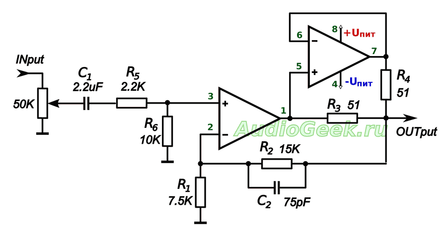
The diagram shows the legs for a dual operational amplifier in a DIP8 package. The circuit is fully working and does not require any configuration.
Let's remove the capacitor from the input
The op-amp amplifies both AC and DC voltage equally well. Capacitor( C1 ) is needed in order to cut off the DC voltage at the input. On the one hand, normal signal sources do not provide a constant output. On the other hand, if it suddenly appears, then it needs to be cut off. Or you might even burn out your headphones.
But people actively don’t want to see extra capacitors in the signal path, so we’ll get out of it.

Reading again " The art of circuit design» Horowitz and Hill, found what I was looking for. To get an AC amplifier, you need to include a capacitor similar to C1 , in series with resistor R1.
In this case, the feedback of the op-amp will work only by alternation and there will be no need for a capacitor at the input. Therefore, you can safely move C1 from the amplifier input to the circuit feedback OU.

Resulting ( R1 , C1 ) will cut off both DC voltage and infra-low frequencies ( <10Гц ). They do not carry useful information, but significantly load the amplifier with current.
Also, such inclusion of a capacitor will reduce the voltage imbalance of the op-amp across the inputs. And it, by the way, is also amplified and mixed into the output signal. In this case, the capacitor in the feedback circuit has practically no effect on the sound, unlike the capacitor at the input. In general, there are only poles from such a rearrangement.
Input resistors
Removing the capacitor from the input forced us to take a closer look at the resistors R5 And R6, remaining at the entrance. Why are they needed at all and how to calculate them?
Resistor R5 called compensating and is necessary to ensure equal resistance between each of the inputs and ground. Its value is defined as the parallel resistance of the resistors R1 And R2 .

However, we consistently with R1 there is a capacitor C1. The resistance of the capacitor depends on the frequency and is added to the resistance of the resistor. The resistance of a capacitor at a certain frequency is determined from the relationship:
R C = 1 / (2 × π × F × C) ,
Where F in Gegritsi, WITH in Farads, and R C in Omaha
To determine resistance R5, First, the resistance values of a capacitor with a capacity of 2.2 μF were calculated at frequencies of 20 Hz and 20 kHz. Then, the values of the compensating resistors were calculated for both cases. It turned out that the resistor resistance R5 must lie between 8.91 kOhm (for 20 Hz) And 6.81 kOhm (for 20kHz). Without hesitation I stuck it in 7.5 kOhm.
We used a capacitor to permanently decouple the inverting input of the amplifier from ground. But the op-amp must be connected to ground via both AC and DC current. This is what the resistor is for. R6 . Its value was chosen to be 75 kOhm. But you can also use 100 kOhm. I would not recommend setting it to less than 75 kOhm, with a variable of 50 kOhm. Together with resistor R5 they will begin to bypass the input variable resistor.

The output has also been slightly changed in the diagram. The values of R3 and R4 were reduced to 10 Ohms, and a resistor R7 with the same resistance was connected in series with them. This should provide better summation of the output signals.
Amplifier power supply
Power quality is very important for sound. This circuit is designed for bipolar supply voltage. This saves us from having to add unnecessary details to the sound path, and is overall better for the sound.
Today there are op amps operating from ±1.5V, but most opamps operate with a bipolar supply voltage from ±3V to ±18V. The optimal voltage is ±12V, which is within the power supply limits of most op-amps.
The exact values of the maximum supply voltage should be found in the documentation for specific microcircuits.

Component quality
It is not necessary to immediately purchase expensive parts. To begin with, you can supply something from the assortment of the nearest radio parts store, and gradually replace them with higher quality components. The board will work on any parts.
Capacitor C1 must be non-polar. Better polypropylene or film. It is better to use ceramic capacitor C2. The accuracy of the capacitors is not very important. but it is better to use with an accuracy of no worse than 5%.
Prices for operational amplifiers vary widely and more expensive does not always mean better sound. To begin with, you can install something inexpensive and accessible, for example, the beloved NE5532 ($0.3). It is highly desirable that it be made by Phillips.
Subsequently, you can play with replacing the op-amp as much as you want. If we consider op-amps of a higher class, then OPA2134, OPA2132, OPA2406, AD8066, AD823, AD8397… have proven themselves well for sound.
I do not recommend ordering microchips from AliExpress or other Chinese stores. There are quite a lot of reviews in which people report that the microcircuits are not original. Yes, the op-amp will work as it should, but it may not be the OPA2134 you ordered, but a rather cheap TL061 labeled OPA2134...
Conclusion
The resulting amplifier circuit, assembled on OPA2132 and operating even at a supply voltage of ±5V, freely swings the rather tight Sennheiser HD380 Pro.
I don’t like to describe the sound in subjective terms like “the highs are crystal clear” or “the bass are warm”; I will only say that when using a good op-amp, this headphone amplifier has sufficient volume and output power. At the same time, it does not require any setup and uses a minimum of parts, while providing decent sound quality.
The considered circuit led to the idea of creating a portable headphone amplifier. That's how it came up . The essence of which is to create a complete design of a portable headphone amplifier with your own hands from scratch.
The material was prepared exclusively for the site
As they say, everything ingenious is simple. This amplifier consists of a minimum of parts, allowing the signal to pass through a minimum of elements, and thereby protecting it from the distortion that these elements can introduce.
The amplifier has a power of 500 mW. The calculated level of distortion when using a chip like OPA2134 is 0.001%. Load resistance 32-300 Ohm.
A volume control is assembled on R1 and R2, or rather it is one double resistor. At the input there is a sandwich of 4.7 and 0.47 µF capacitors, which allows you to achieve maximum linearity. Inverting amplifiers with a gain equal to 4 are assembled on IC1.1 and IC1.2. Next are transistor repeaters. OOS is formed by R6 and R5. R11 and R12 limit the current flowing from the op-amp to the bases of the repeaters; this makes life easier for the op-amp, and there is a little less distortion. R7, R8, R9, R10 limit the current of the repeater transistors and protect them from through currents. The circuit is powered by bipolar voltage and has built-in filtering circuits on stabilizer chips 7812 and 7912. At the output there are capacitors that prevent direct voltage from reaching the output.
You can use LM358 as IC1 as the most affordable option, but for high-quality sound I advise you to use a more expensive analogue.
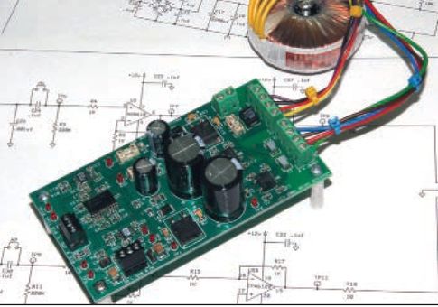
The printed circuit board includes all elements except the connectors. Its dimensions are only 50x50mm. This size was chosen with the goal of ordering boards from the Chinese in the future, fitting into the cheapest lot measuring 5x5cm. In general, this project was originally planned to be used as a commercial development, but I still decided to make it publicly available.
The first board was made using the plotter application method:

The shaft is small, so fastening is carried out using a standard variable resistor nut. The assembled device looks like this:

List of radioelements
| Designation | Type | Denomination | Quantity | Note | Shop | My notepad |
|---|---|---|---|---|---|---|
| IC1 | Operational amplifier | OPA2134 | 1 | LM358 | To notepad | |
| Linear regulator | LM79L12 | 1 | To notepad | |||
| Linear regulator | LM78L12 | 1 | To notepad | |||
| VT1, VT3 | Bipolar transistor | BC547 | 2 | To notepad | ||
| VT2, VT4 | Bipolar transistor | BC557 | 2 | To notepad | ||
| R1, R2 | Variable resistor | 50 kOhm | 2 | To notepad | ||
| R3, R4 | Resistor | 47 kOhm | 2 | To notepad | ||
| R5, R6 | Resistor | 200 kOhm | 2 | To notepad | ||
| R7-R12 | Resistor | 10 ohm | 6 | To notepad | ||
| 1000 µF | 4 | To notepad | ||||
| Electrolytic capacitor | 100 µF | 2 | To notepad | |||
| Electrolytic capacitor | 10 µF | 2 |
According to the results survey Earphones assembled on “semiconductors” won. Therefore, we will begin our line of construction sets with them.
I'd like to start with a few very simple diagrams. They are not suitable for the role of a designer, but their consideration will perhaps lead us to a scheme that, in our opinion, makes sense to form the basis of a designer.
So, let's begin.
In the previous article, we already said that a headphone amplifier must first of all solve two main problems.
Firstly, it must unload the output of the signal source. Operating an audio output with a low-impedance load leads to a sharp increase in distortion (due to high current load) and a deterioration in the frequency response (low-frequency and sometimes high-frequency rollover). The use of a current buffer amplifier prevents these phenomena.
Secondly, to ensure normal volume on high-impedance headphones (and volume reserve on low-impedance ones), the earpiece must have some voltage gain.
When using low-impedance headphones, additional amplification is not always necessary. In such cases, the amplifier is used as a current buffer. Sometimes the simplest schemes can be used in this capacity. For example, like in the picture. These are ordinary repeaters. They can be assembled using both bipolar and field-effect transistors.


The most primitive diagram is on the left. Simplicity is its main advantage (perhaps its only one). High nonlinearity, high output impedance, very low efficiency (even by the standards of class A circuits), etc. make it not very interesting from a practical point of view.
It makes sense to complicate it a little. Let's replace the emitter resistor with a current source (diagram on the right). Such a scheme already has a right to life. It can achieve low output impedance, increase the amplifier's ability to deliver current to the load, significantly improve linearity, etc.
It is worth saying a few words about the nonlinearity of a circuit with a current source. In general, linearity is not very high and depends on the quiescent current, headphone resistance and the type of transistor used. The overall harmonic level can reach tenths of a percent. But the distortion spectrum is favorable, short, with a predominance of the second harmonic. For example: with a quiescent current of 200mA (32 Ohm headphones), you can expect the level of the second harmonic to be about 0.1%, the level of the third – 0.01% and the non-detectability of harmonics of higher orders. Such an amplifier should sound clean.
When working with high-impedance headphones (and often low-impedance ones), there is a need to amplify the signal. Providing volume headroom has a very beneficial effect on playback quality. Let's consider the simplest scheme. (see picture)

Such circuits are sometimes used even to work with full-fledged acoustics. The decision is not for everyone. The advantages of the circuit are simplicity and a favorable distortion spectrum (second harmonic). The coloration of the sound is quite strong, and its character depends on the selected transistor, the quiescent current and the load resistance. Most likely not suitable for lovers of clean, accurate sound.
A high level of harmonics is a consequence of unsatisfactory operation of the cascade with a low-impedance load. If we put an additional buffer between the amplifier output and the headphones (for example, the one discussed at the beginning), we will get a new circuit.

The linearity of the voltage amplifier will increase significantly, and the sound characteristics of the entire circuit will be determined mainly by the output buffer stage.
In most cases, this simple circuit will be enough to match the headphones with the laptop sound card. At the same time, the playback quality will increase.
Now let's talk about further ways to improve the characteristics of the amplifier.
This problem can be solved head-on. For example, by increasing the quiescent current or selecting a more linear transistor. You will have to pay for this in terms of complexity and cost. The sizes will also increase. This method can significantly improve performance, but there are other, less straightforward ways to improve.
A more common way to increase objective parameters is to significantly complicate the scheme and introduce a common operating system. The circuit remains compact and economical, but difficult to replicate, assemble and configure. At the same time, its price will also increase.
Therefore, in our opinion, none of these options is suitable for the designer. They lack versatility.
A more universal solution could be a circuit using an op-amp with an additional output buffer. An example version is shown in the figure.

Its main property is a very clear sound. And this is exactly what, in our opinion, a transistor amplifier should be. And for an embellished sound, it is better to use hybrid amplifiers.
The circuit itself leaves some freedom in sound settings. This is also a replacement for op-amps (less noisy, more/less fast, etc.). If desired, replace the output transistors, select their operating mode (which affects the colors introduced into the sound).
By changing the sealing, you can cover the OS of the entire amplifier or just the op-amp. Each of the options is interesting in its own way. When covering the entire OS amplifier, very high linearity is achieved, the total harmonic distortion will be thousandths of a percent. Excluding the output buffer from the OS loop will lead to an increase in the second harmonic (“euphonic” distortion). In addition, there will be some other changes that affect the sound. It is quite possible that someone will find this sound more interesting. The quiescent current of the output stage can be selected to suit the requirements of the headphones used (by default I would set it to 200mA).
Among other advantages of such a circuit, I would note the ability to work in a wide range of supply voltages (without any settings or changes), ease of assembly and configuration.
Someone may also find it useful that the device can be easily turned into a high-quality power amplifier (class A) working for acoustics. But that, as they say, is another story (if anyone is interested, I’ll tell you about it separately).
The sound quality of this earphone has been tested and is high. A similar circuit is used in the amplifier, the appearance of which was shown in the photographs that accompanied all our notes about the designer.
As they say, I have everything. I would like to know what you think about all this?
Best regards, Konstantin M
All articles dedicated to the Gamma project can be found through the navigator
You can order the “Gamma” amplifier designer on our website: AL “Philosophy of Sound”
Community for discussing constructors - "Electronic constructors". Join us.
Due to the purchase of a new sound card without a headphone output, I had a need for a decent quality headphone amplifier capable of driving my favorite TDS-4. The amplifier had to be compact, easy to assemble and set up, with low noise and distortion. As a result, the assembled amplifier met all the above requirements.
The characteristics of the amplifier were measured using the RMAA 6 program. A single channel layout was tested (the program worked in MONO mode), measurement results:
Frequency response unevenness (in the range 40 Hz – 15 kHz), dB: +0.05, -0.74
Noise level, dB (A): -90.9
Dynamic range, dB (A): 90.9
Harmonic distortion, %: 0.0014
Intermodulation distortion + noise, %: 0.010
Intermodulation at 10 kHz, %: 0.0084
The amplifier is built according to the op-amp + output transistor buffer circuit. The op amp provides the high open-loop gain needed to suppress harmonic distortion with deep feedback. The output buffer performs current amplification by matching the low resistance of the headphone coil to the low-power output of the op amp. The circuit uses dual high-speed op-amp K574UD2. The signal from the source through the isolation capacitor C3 and resistor R1 is supplied to the non-inverting input of the op-amp. Resistor R4 sets the amplifier's DC operating point. Elements C1, C2, R2, R3 provide frequency correction of the op-amp. The output buffer is made according to a “parallel” circuit. This circuit was chosen because it lacks the transient distortion associated with conventional push-pull circuits. When using transistors with similar parameters, the voltage drops at the base-emitter junctions of the pre-final and final cascades are mutually compensated. Buffer transistors, being installed on a common heat sink, mutually thermally stabilize each other. The op-amp and buffer stage are covered by a common 100% OOS for direct and alternating current, the gain of the circuit is 1.
It is advisable to use film capacitor C3. C1, C2, C6, C7 – ceramic. All resistors are MLT-0.125 type (or imported analogues). Transistors VT1 KT315G, VT2 KT361G, VT3 KT815G, VT4 KT814G. It would be preferable to use transistors KT815G and KT814G as VT1 and VT2, for reasons of identical parameters and the ability to easily organize thermal contact of all four buffer transistors. The op-amp can be replaced with any other high-speed one with a corresponding change in the set of corrective elements and the layout of the printed circuit board. The amplifier is powered from a bipolar unstabilized power supply. The power supply uses a 220/20 transformer tapped from the midpoint of the secondary winding. Any diode bridge for voltage 50V and current up to 1A. It is possible to use diodes of the 1N4001-1N4007 series. The capacity of capacitors C4, C5 is at least 1000 µF (I used 4700 µF)
A properly assembled amplifier does not require adjustment. It is necessary to check the current consumption (about 30 mA for a two-channel amplifier) and the constant voltage at the output.
The parts of the amplifier and power supply are placed on a common board measuring 35x78mm. The transistors of each channel are attached through insulating gaskets to a common U-shaped heat sink. The area of the heat sink is unimportant, the main thing is that it ensures thermal contact of the transistors.
The printed circuit board is single-layer with jumpers, laid out in Sprint Layout 5. In the author’s version, non-foil PCB was used, the parts were installed in holes, the pins were connected with copper wire.

Literature:
Amplifier block of an amateur radio complex. A. Ageev, Radio No. 8 1982
The Sapphire Desktop Headphone Amplifier – http://phonoclone.com/diy-sapp.html
If you are the lucky owner tube amplifier, then most likely, if you want to listen to your favorite songs alone, through headphones, you are faced with the inconvenience caused by the lack of output to headphones.
And owners of expensive or not very expensive smartphones and tablets also have a hard time - these devices are most often not able to pump high-quality high-impedance headphones. Therefore, your favorite compositions sound completely different from how they sound on professional equipment.
Of course, if you are a true music lover and music is more valuable to you than money, then nothing will stop you from buying a pre-amplifier for $6,000, a headphone amplifier for $5,000, and the headphones themselves for $2,000. And plunge into nirvana... However, if the money situation is not so rosy, or you like to do everything yourself, then it turns out that you can build a high-quality headphone amplifier for only... $30.
Why do you need it???
Do you need a precision amplifier? It depends on your musical preferences and habits. If you are used to listening to music “on the run”, that is, from portable devices while walking, jogging, in the gym and other similar places, then the project described below is not for you. Just try to choose headphones that match your device with the most suitable characteristics and sound.
You should do the same if you like musical styles where there is strong signal distortion, such as rock, heavy metal and the like.
However, if you prefer to listen to music in a quiet, comfortable environment at home or in the office, and your tastes gravitate toward live and natural music such as classical, jazz, or clean vocals, then you will appreciate the sound quality and accuracy of the mix. precision amplifier plus high quality headphones.
Options
Let's say you decide that you need a headphone amplifier. What's the next step? On the Internet you can find a lot of projects using the ubiquitous LM386. The microcircuit has become popular due to its high reliability, low cost, ability to work with single-polar power supply and a small number of external elements. Such amplifiers usually work well with inexpensive headphones, but all these advantages pale when compared to the noise and distortion levels of the LM386 and a well-designed discrete or ASIC amplifier.
If you have about $30 and are not afraid of working with surface mount elements (SMD elements), then the project presented here is exactly what you need.
Ideas and scheme
When designing this scheme, the following points were taken into account:
- The amplifier must be driven by the relatively high impedance output of a tube preamp or electric guitar amplifier. In other words, the input impedance must be easily tunable for sources with different output impedances.
- small number of components. Therefore, microcircuits were chosen instead of transistors.
- low gain and power. Needs to be rocked sensitive dynamic headphones, not the speaker system.
- The amplifier must be able to handle high impedance headphones. The author uses Sennheiser HD 600 (resistance 300 Ohms).
- get the lowest possible noise and distortion.
Schematic diagram precision headphone amplifier shown in the figure:

Click to enlarge
When developing this design, microcircuits from such manufacturers as National Semiconductor, Texas Instruments and others were considered. A lot of useful information was found on the Headwize resources and DiyAudio forums.
As a result, the choice fell on a precision headphone driver from Texas Instruments TPA6120A2 and operational amplifiers AD8610 from Analog Devices for the input buffer.
The circuit turned out to be relatively simple, with bipolar power supply. If you are sure that there is no DC component at the output of your signal source, then the coupling capacitors (C24 and C30) can be excluded from the path using jumpers H1 and H2.
The power supply provides ±12V output voltage at a load of up to 1A. Its diagram is shown in the figure:

Click to enlarge
Often in audiophile designs, the cost of the power supply is several times higher than the cost of the amplification part itself. Here it turned out a little better - the cost of the elements for the power supply is approximately $50 and the most expensive elements here are the transformer and electrolytic capacitors. You can save a little if you replace the toroidal transformer with a regular W-shaped one, abandon the LEDs and fuses at the output of the unit.
We tested a version with separate stabilizers for each TPA6120A2 channel (the microcircuit has separate power pins for each channel). It was not possible to hear or measure the difference, which made it possible to significantly simplify the power supply.
Since all the microcircuits used in the amplifier have a low sensitivity to noise and interference in the power supply circuits, as well as a high level of suppression of common-mode interference, the use of standard integrated stabilizers in the power supply turned out to be sufficient to obtain high performance.
TPA6120A2
The Texas Instruments TPA6120A2 is a high-quality, high-fidelity headphone amplifier. It uses an amplifier architecture with differential input, single-ended output, and current feedback. It is thanks largely to the latter that low distortion and noise, a wide frequency band, and high performance are obtained.
The microcircuit contains two independent channels with separate power pins. Each channel has characteristics:
- output power 80 mW into a 600 Ohm load with ± 12 V power supply at distortion + noise level 0,00014%
- dynamic range over 120 dB
- signal/noise level 120 dB
- Supply voltage range: ±5V to ±15V
- output voltage slew rate 1300V/µs
- protection against short circuit and overheating
For comparison, the distortion + noise level of the “folk” LM386 microcircuit is 0.2%. Although, of course, high parameters do not guarantee high-quality sound. To obtain the maximum result, you must take into account the manufacturer’s recommendations on the selection of external elements and PCB topology. All this can be found in the technical documentation for this chip.
AD8610
The AD8610 chip from Analog Devices is an operational amplifier with field-effect transistors at the input, which gives low offset and drift voltages, low noise levels, and low input currents. In terms of noise level and slew rate of output voltage, these operational amplifiers are in perfect harmony with the TPA6120A2.
However, don’t be lazy and try replacing them with other op-amps. According to the pinout arrangement, the AD8610 is compatible with other audiophile microcircuits. Moreover, many music lovers claim that they hear a difference in the sound of the op-amp!
Passive Components
Not all resistors are the same! And if your budget allows, use metal film resistors in this design, which are somewhat more expensive, but have lower noise and higher stability. If you want to save money, metal film resistors should be installed at least in the input circuits (for the AD8610), where the sensitivity to noise is the highest.
It is better to install film capacitors on the signal path C23, C24, C29, C30. The manufacturer recommends ceramic capacitors for power supply circuits of microcircuits.
The main requirement for signal connectors is reliable contact. In his design, the author used a regular “jack” to connect headphones and gold-plated RCA connectors with Teflon insulation to connect the signal cable.
The circuit diagram shows a version of the amplifier for operation from a tube preamplifier, in which the volume is adjusted. If the design is intended to be made more flexible and universal, then, of course, it is advisable to provide its own volume control at the input. To achieve maximum quality and not to degrade the characteristics of the amplifier, a high-quality potentiometer should be used here.
The budget version can be products from Alpha or RadioShack costing about $3. For $40 you can purchase an audiophile-grade product from ALPS. The best solution is to use a strip attenuator from DACT or GoldPoint. Their cost is approximately $170. By the way, on eBay you can find similar Chinese-made attenuators for only $30. The potentiometer rating can be in the range of 25-50 kOhm. The use of a step attenuator, in addition to the convenience of volume control, additionally guarantees identical adjustment in both stereo channels, which is especially important in a headphone amplifier.
Design
All structural elements (except for the power transformer) are placed on one printed circuit board. If you decide to use an external power supply or assemble it in a different way, about 70% of the PCB will remain free.
The layout of the elements is shown in the figure:

Click to enlarge
The figure shows a drawing of the printed circuit board from the parts side:

Click to enlarge
The figure shows a drawing of the bottom side of the printed circuit board:

Click to enlarge
Printed circuit board drawings in the popular SLayout format can be picked up
The main installation feature: on the case on the bottom side of the TPA6120A2 there is a contact pad of approximately 3x4mm. She must be soldered to the area on the printed circuit board under the chip, which serves as a heat sink.
Photo of the finished structure:
When you turn it on for the first time, you should remove the two fuses at the output of the power supply and make sure it is working. If the output voltages are normal, replace the fuses. The amplifier itself does not need adjustment.
The board can be placed in a case of suitable dimensions, preferably metal, to shield it from external interference.
Conclusion
Subjectively, the amplifier sounds on par with professional studio equipment. When compared to the LM386, this design showed a smoother, cleaner and more detailed sound.
The scheme turned out to be quite flexible and easily customizable to suit various needs. For example, the author himself assembled two copies of the amplifier. One according to the above diagram for operation in conjunction with a tube preamplifier. The second copy was designed to work with a smartphone and a guitar amplifier, so it was supplemented at the input with a high-frequency noise filter and a volume control. In addition, to increase the gain (the smartphone produced an insufficient signal level), the values of resistors R6 and R14 were changed to 2 kOhm.
By changing the values of these resistors, you can change the gain within a wide range.
A variant of the amplifier printed circuit board from our “Martian friends”, designed for installing elements in “standard” packages (there are no DIP packages used in the design of microcircuits):
Animated demonstration of the board from all angles


