The most useless device
Surely you have seen what the “Most Useless Device” looks like, if not, then you should watch a video of its operation. It's unforgettable!
An entertaining little thing :) And most importantly, it can attract the attention of guests for a long time.
Usually, it’s these kinds of interesting little things that you want to make with your own hands.
I must say that making such a device is not difficult. You can get by with what you have on hand.
Here's the principle electrical diagram the most useless device:
A conventional servo can be used to drive the switch pusher. Moreover, a “killed” servo will do. Anyway, all electronics are removed from the original servo and only the motor and built-in gear reducer are used.
In addition, you will need a six-pin On-On switch and a microswitch. By the way, the latter are usually used for keystrokes in computer mice.
The most difficult thing in making such a machine is making the body. A schematically operating device can be made of thermoplastic. Subsequently, it is easy to complete the case from wood or plastic.

Watch the video instructions for making the most useless thing. This instruction shows how to do it and what to attach where.
The manufactured device is not as beautiful as in the first video, but it works and is just as useless as the original :)
Pavel comments:
Oh cool! I'll go buy everything I need)
Andrzej comments:
A funny homemade product. There’s no shame in giving something like this, and you can get a lot of entertainment out of it - just who knows how much!
Arduino + two servos + charging board + boost converter board + old battery + a bunch of radio components + piece of plywood + toggle switch = an idiot's dream come true!
Lots of text for those who like to read. Lots of spoilers for those who like to read diagonally. Video, for those who love videos. Sketch for those who like to immediately copy and run “on the knee”. Photo, photo, photo. Cat, for cat lovers.
Not really a disclaimer
This is my first project, apart from blinking LED, Hello world, etc. According to tradition, you must first sprinkle ashes on your head to ensure that the code is far from perfect and be sure to get involved in a dispute about this. And also regarding the partial copying of code from another project, ask not to hit too hard, etc. But this won't happen. The code is perfect! Because it works, I like it and I made it for myself.
I’ll give advice to those who are interested: don’t be afraid, join the fight, shovel mountains of code, build your own mega-pyramids from different operators. Over time, style, sophistication, and ideal will come.
As long as there is space in the controller's memory, you are not afraid of anything. If you hit a wall, you will optimize. And this is also development. It's important.
A big book on C programming - yes, useful. But, at first, it is much more useful to have a short reference on commands on hand and keep in your bookmarks several links to working with simple examples, libraries, etc., like , or the same Amperka.
Also, flowcharts help me a lot. Rectangle, diamond, oval. Anyone who has encountered it understands. I'm doing one project now - I can't do it without a flowchart. For me, it’s better to draw for several days - redraw on paper in order to more clearly imagine the entire flow of the program, than to jot down a bunch of code and get stuck in it, because... I do not have the ability to cover the entire code with the power of my programming thoughts, due to my limited experience.
For those who want to repeat it or do it their own way, I will answer all questions.
I will not enter into empty disputes about my writing, style, design, code and necessity of the product, etc. If I made a serious mistake somewhere in the review, I’ll correct it or add it.
You can Google what “The Most Useless Device” is. I came across it by accident. This code was taken as a basis, because it didn’t launch on its own, and I wanted to make my own scripts.
Lyrical digression
They say that after forty, especially when you are already very much after forty, you need to try to “flex” your brain. And that learning languages is the best warm-up. And not only at that age. I'm not very good at languages, but the Health magazine seems to advise... In general, I decided to learn something new for myself. Electronics is not new to me, although I have forgotten most of it, but programming has never been familiar to me. I was afraid of him. But here many signs from above coincided: the magazine “Health”, which recommends learning something new, a long-standing dream to understand (at least a little) programming (at least something) and youtube, in which only the lazy do not talk about how to blink an LED using smart fee for a dollar and a penny.
Before this, I managed the LED blinking pretty well using two transistors, a capacitor and a pair of resistors, but now, they say, it’s not comme il faut. So you need to be in trend.

I really liked this useless, in the literal sense of the word, device. I saw it and fell in love. I want it, that’s all! Like a child's dream! But age has made its own adjustments. I want to make it myself, not buy it. Especially since it's on sale simple devices. I came across an “intellectual” one, but I couldn’t find anything like it on sale. Moreover, it must be done!
And again, Arduino. And I don’t boom-boom in it. So we need to figure it out. Aliexpress to the rescue. I started with Arduino. I understood that the path to study would be thorny and sacrifices were inevitable. So I ordered five different ones. Let them burn, if anything. Debugging of the circuit took place on Uno from another seller. But, since this particular board was in the final device, it was included in the title.
In addition to Arduinos, I ordered a huge amount of all kinds of junk, both Arduino-compatible and near-Arduino. Here I will only tell you about what was useful in this product.
Arduino Pro Mini

Delivery is fast, packaged in a standard antistatic bag and envelope with a pimpled inner surface. The seller is sociable, Russian-speaking.
On a 328 chip. 3.3 volts, 8 MHz. Why is this so? Yes, by mistake. I wanted 5 volts, 16 MHz, but bought this one. It's my own fault. However, for this project it is not critical - I installed an extra voltage converter. That's all. I didn't find any huge differences from other Minis. The brand difference is black textolite(?). Of the jambs: the RAW pin does not work on the board. But that didn’t stop either. Although, a 3.3 V converter could save money with it. The combs are not soldered. The board is made well.
Why so short? Because there is already bias about this seller and his fees (clause 18). Those who want can find it easily. There is no point in retelling it. I also added my two cents in the comments to it. And I corresponded with the seller a lot.
Servo drive SG90
$3.2 per lot of two pieces.
There is nothing special to describe. Weak servo drive with average positioning accuracy, which is highly dependent on the speed of movement. But it's cheap. For the lid drive - more than enough, for the “hand” - on the verge of possibilities. It requires 5 volts to operate, but 3.3 is sufficient for control. I tried to control it through the converter and directly from the Arduino - there is no difference. Therefore, the level converter saved money.
Charge controller and power converter
$2.28 for five pieces. With protection. While charging, the red LED is on; when charging is complete, the blue LED is on. There was a review here.
$0.50 each. Delivery, however, is paid, but I bought a whole bunch of other things from this store, so delivery was not annoying. The USB socket was removed to lighten the weight))) The output produces 5.12 volts.

I took it offline. A little tight. To facilitate the operation of the servo, it was possible to disassemble it, shorten the spring or replace it with a weaker one. But laziness won. I put it like this. True, I had to write in the code additives to the angle of rotation of the servo at high speeds.
TTL converter
$1.5 per piece. Actually, I ordered it first. It's half the price. But, for some strange reasons, he died a heroic death. I still don’t understand how I killed him. For this reason, the project stalled for a month until a new, more advanced one arrived - no need to press reset. Isn't this progress?
The rest is from storage
Voltage regulator 1117T-3.3V in TO220 housing, capacitors 1500.0x6.3 and 470.0x16, two 0.1 μF capacitors, white LED and microswitch from a children's car, 220 Ohm resistor. The battery had been lying around unused for several years. I once took apart a burnt (literally) portable DVD player. The only good thing there was the batteries that survived. Here is one of them that came in handy. Voltage 3.7 V, I didn’t find the capacity in the labeling.
Glue gun, elastic band for money, two hooks from... a bra (thanks to my wife. Darling, I love you!), two furniture dowels, four screws, four adhesive bumpers for furniture doors, a piece of a breadboard, wires, connectors.
The situation with the hull was more complicated. Many boxes have been tried. The plastic box from the Tissot watch turned out to be fragile, partly cardboard. But the metal curtains from it came up. There's even one left in stock. I tried ready-made perfume cases, a wine box, and a candy box. In the end, I decided to do it myself.
High-quality plywood, most likely birch, was found in a children's burning set. The child has grown up - the set remains. On one side there was a drawing, but the other side looked to put it bluntly, excellent
Simply put, great
At school we had a Trudovik. Aged. In general, he is a wonderful person. He was respected. When we went through electricity, using the example of a battery, a light bulb and a key, he gave us a lecture.
“There is current in the battery. Now he comes out of the positive and follows the wires. It goes, goes, suddenly bam - the key is on the way. And the key is open. Tok understands that there is nowhere to go further. He turned around and went into the battery. And the light doesn't light up. We close the key. The current started flowing again, reached the key, passed through it, passed through the light bulb and returned to the battery. And the light bulb is lit, frankly speaking, perfectly.” Since then, there has been such a phrase in the lexicon, as a synonym for something unexpectedly successful.

I tried cutting plywood with a hacksaw and a jigsaw, but it didn’t work. Chips, which are then difficult to remove, and an uneven edge. I found a way out - a sharp stationery knife. It cuts through half of the plywood on one side and half on the other. Then a little sanding and everything is fine. But, with a good metal ruler and a constantly sharp blade, you get a perfect cut and a straight line.
Of course, not without its flaws - under the Hand made sticker there is a banal hole hidden. I drilled it in the center for the toggle switch. But the servo didn’t fit. I had to move the toggle switch to the side and close the hole. Such difficulties do not frighten me.
I don’t see the point in describing every sneeze involved in making the device. I will describe some points. And he who has hands, let him do it.
I assembled the box using hot melt glue. I didn't spare the glue itself. Holds up perfectly. Doesn't creak, doesn't play. Fast, cheap and cheerful. And in general, as you noticed, almost everything is held together by this glue. I recommend. It greatly speeds up the assembly process. I glued the switch-off microphone from the inside to the left wall - it can be seen a little in the photo.
The lid was attached to the curtain.

I suffered with the veil. I experimented a lot. I wanted the lid to be located on top of the box, and not inside. I even bent several versions of staple curtains from paper clips. Poe later remembered that during the experiments, the curtains from the box of Tissot watches caught his eye. So good, Swiss (Chinese?).
The veil is an important thing. Its quality is very important for the overall external beauty of the device.
The main toggle switch needs to be softer, then it will work easier.
The lid is returned to the closed position by an elastic band. There is no need to choose it very rigid - the servo will handle it, but if the curtain is centrally located, the lid will warp.
In the case of plywood, varnishing is mandatory - it gets very dirty. I used clear tsapon varnish. Simply because there was no other one at hand.
It is better to position the servo that controls the “hand” differently. Not on the side, but in front of the toggle switch. Then the “arm” may be simpler to manufacture - L-shaped, instead of U-shaped. The width of the box can be reduced and the toggle switch can be placed in the center.
It is better to rotate the lid servo 180 degrees, then in the code it will be easier to associate the degrees of this servo with the operation of the lid. For me it’s the other way around, so opening means decreasing degrees. But for the “hand” it’s the other way around. And it is more correct to push the lid from the same side from which the elastic band is pulling it back.
The box should not be made too small. It won't be convenient to use. But a flatter one is acceptable. The box is light and if it is flatter it will be more stable. It will be more convenient to push the toggle switch with your finger without holding the box.
I made something like a shield out of two pieces of a breadboard. Soldered into Arduino without connectors. Tightly. I do not mind.

But I made all the peripherals on connectors. It is more comfortable.
A large capacitor to power the Arduino (3.3 volts) is required. Without it, the Arduino hangs.
I do not have assembly drawings of the device. It is so simple that many others can be used simple solutions, on which all mechanics are based. In the video, both mine and other similar devices, you can see the drive options used.
#include
The sketch suggested by the author from the link at the beginning of the review did not work for me. And I was not yet the pro that I am now)))))))
In general, I began to understand. As a result, based on someone else’s, I made my own sketch. Added anti-bounce protection. It would have been easier, of course, to install a resistor with a capacitor, but I really wanted to program it.

In principle, the scheme is clear from the sketch. But I’ll bring her anyway. Sorry for the quality - as best I could. I took a slightly different converter board - I didn’t find it needed in the front view.
There are no special explanations for the sketch. Perhaps the moment of adding a few degrees of rotation angle, when the servo speed is high. I noticed that if the “hand” jumps out suddenly, it does not turn off the toggle switch. This is obviously due to the poor quality of the servos. Therefore, you need to add a little to the angle of departure of the “arm”. I suspect that with repetition, these additional degrees may be different for you. Depends on the shoulder of the “arm”.
And about the programs. So far there are six programs. Called through random number generation. Moreover, simple programs (0, 1 and 2) are called more often than ordinary ones. It seemed to all my testers that more sophisticated programs should be a rare pleasant bonus, then a certain intrigue appears. So I did.
For lovers of numbers, the size of the box is: length - 150mm, height - 70mm, width - 65mm.
Youtube has greatly degraded the quality. If you need to look at the original, download it. 21 MB.
Here the sketch has been modified to allow you to see all six programs in turn so that you have an idea of them all. In life, as I wrote, they have a pseudo-random order.
Charging is done via micro-USB with a regular mobile charger. Battery life is highly dependent on frequency of use. Sometimes for several days, and sometimes I “kill” in a day.

Lastly.
The project, however, can be further developed and improved. You can come up with new scenarios. You can add a tweeter and voice the device. For example, let him “growl”, like get angry, if the time between turning off and turning on the toggle switch is very short. You can, as in the original project, add movement of the box in different directions.
You can build in a check for the case when the “hand”, for some reason, did not turn off the toggle switch (for example, in the cold, the servo does not reach the desired angle quite a bit) and adjust the angle one at a time, writing some kind of “nervous” message specifically for such a case » shutdown program. You can install the Nano and program via USB without disassembling the device each time. I liked the review +123 +232
Arduino + two servos + charging board + boost converter board + old battery + a bunch of radio parts + piece of plywood + toggle switch = an idiot's dream come true!
Lots of text, for those who like to read. Lots of spoilers for those who like to read “diagonally”. Video, for those who love video. Sketch, for those who like to immediately copy and run on their knees. Photo, photo, photo. Cat, for cat lovers.
Not really a disclaimer
This is my first project, not counting LED flashing, Hello world, etc. According to tradition, you must first sprinkle ashes on your head, on the subject of the fact that the code is far from perfect and you must get involved in a dispute about this. And also regarding the partial copying of code from another project, ask not to hit too hard, etc. But this won't happen. The code is perfect! Because it works, I like it and it was made for myself.
I’ll give advice to those who are interested: don’t be afraid, go into battle, dig through mountains of code, build your own mega-pyramids from different operators. With time, style, sophistication, and ideal will come.
As long as there is space in the controller's memory, you are not afraid of anything. If you hit a wall, you will optimize. And this is also development. It's important.
A big book on programming in C - yes, useful. But, at first, it is much more useful to have a short reference book on commands on hand and keep in your bookmarks several links to work with simple examples, libraries, etc. de arduino-diy.com, or the same Ampere.
And also, flowcharts help me a lot. Rectangle, diamond, oval. Those who have encountered it understand. I’m doing one project now - I can’t do it without a flowchart. For me, it’s better to draw and redraw on paper for several days in order to more clearly imagine the entire progress of the program, than to sketch out a bunch of code and get stuck in it, because... I do not have the ability to cover the entire code with the power of my programming thoughts, due to my limited experience.
For those who want to repeat it or do it their own way, I will answer all questions.
I will not enter into empty disputes about my writing skills, style, design, code and need for the product, etc. If I made a serious mistake somewhere in the review, I will correct it or add it.
What is “The most useless device” you can google yourself. I came across him by accident. This code was taken as a basis, because... It didn’t start on its own, and I wanted to make my own scripts.
Lyrical digression
They say that after forty, especially when you are already very much after forty, you need to try to “warm up” your brain. And that learning languages is the best warm-up. And not only at that age. I’m not very good at languages, but the magazine “Health” seems to advise... In general, I decided to learn something new for myself. Electronics are not new to me, although I have forgotten most of it, but programming has never been familiar to me. I was afraid of him. But here many signs from above coincided: the magazine “Health”, which recommends learning something new, a long-standing dream to understand (at least a little) programming (at least something) and YouTube, in which only the lazy don’t tell you how to blink an LED using smart payment for a dollar and kopecks.
Before this, I did a good job of controlling the blinking of the LED using two transistors, a capacitor and a pair of resistances, but now, they say, this is not comme il faut. So you have to be in trend.

I really liked this useless, in the truest sense of the word, device. I saw it and fell in love. I want it, that’s all! Like a childhood dream! But age has made its own adjustments. I want to make it myself, not buy it. Moreover, simple devices are on sale. I came across “intelligent”, but I couldn’t find anything like it for sale. Moreover, we must do it!
And again, Arduino. And I don’t boom-boom in it. So we need to figure it out. Aliexpress to help. Started with Arduino. I understood that the path to study would be thorny and sacrifices were inevitable. That's why I ordered five different ones. Let them burn, if anything. Debugging of the circuit took place on Uno from another seller. But, since it was this board that ended up in the final device, it was included in the title.
In addition to the Arduino, I ordered a huge amount of all kinds of junk, both Arduino-compatible and near-Arduino. Here I will only tell you about what was useful in this product.
Arduino Pro Mini

Delivery is fast, packed in the form of a standard anti-static bag and an envelope with a pimpled inner surface. The seller is sociable, Russian-speaking.
On a 328 chip. 3.3 volts, 8 MHz. Why is this so? Yes by mistake. I wanted a 5 volt, 16 MHz, but I bought this one. It's my own fault. However, for this project it is not critical - I installed an extra voltage converter. Actually that's all. I didn’t find any huge differences from other Minis. The brand difference is black textolite(?). Among the shortcomings: the RAW pin does not work on the board. But that didn’t stop either. Although, a 3.3 V converter could save money with it. The children are not wired. The payment was made well.
Why so briefly? Because there is already bias about this seller and his fees (clause 18). Those who want will find it easily. There is no point in retelling it. I also added my two cents in the comments to him. And I corresponded with the seller to my heart's content.
Servo drive SG90
$3.2 per batch of two pieces.
There is nothing special to describe. Weak servo drive with average positioning accuracy, which strongly depends on the speed of movement. But it's cheap. For the lid drive - more than enough, for the “hand” - on the verge of possibilities. To work you need 5 volts, but for control 3.3 is enough. I tried to control it through the converter and directly from the Arduino - there is no difference. Therefore, the level converter saved money.
Charge controller and power converter
$2.28 for five pieces. With protection. While charging, the red LED is on, the end of charging is the blue LED. There was a review here.
$0.50 each. Delivery, however, is paid, but I also took a whole bunch of all sorts of things from this store, so delivery was not stressful. The USB socket has been removed to make it lighter))) The output produces 5.12 volts.
I took it offline. A little tight. To make the work of the serva easier, it was possible to disassemble it, shorten the spring or replace it with a weaker one. But laziness won. I put it like this. True, I had to write in the code additions to the angle of rotation of the servo at high speeds.
TTL converter
$1.5 per piece. Actually, I ordered it first. It's twice as cheap. But, for some strange reasons, he died the death of the brave. I still didn’t understand what I used to kill him. For this reason, the project stalled for a month, until a new, more advanced one arrived - no need to press reset. Isn't this progress?
The rest is from stock
Voltage regulator 1117T-3.3V in TO220 package, capacitors 1500.0×6.3 and 470.0×16, two 0.1 µF capacitors, white LED and microswitch from children's th machine, resistor 220 Ohm. The battery was lying around for several years without use. I once took apart a burnt (literally) portable DVD player. The only good thing there was that the batteries survived. Here is one of them that came in handy. Voltage 3.7 V, I didn’t find the capacitance in the marking.
A glue gun, an elastic band for money, two hooks from... a bra (thanks to my wife. Darling, I love you!), two furniture dowels, four screws, four adhesive bumpers for furniture doors oh, a piece of a breadboard, wires, connectors.
The situation with the body was more complicated. Many boxes were tried. The plastic box from the Tissot watch turned out to be fragile, partly cardboard. But the metal curtains came away from her. There is even one left in stock. I tried ready-made perfume cases, a wine box, and a candy box. In the end, I decided to do it myself.
High-quality plywood, most likely birch, was found in a children's burning set. The child has grown up - the set remains. A drawing was applied on one side, but the other side looked to put it bluntly, great
To put it bluntly, great
At school we had a labor worker. At age. In general, he is a wonderful person. He was respected. When we went through electricity, for example a battery, a light bulb and a key, he gave us a lecture.
“There is current in the battery. Now he comes out of the blue and follows the wires. It goes, goes, suddenly bam - the key is on the way. And the key is open. Tok understands that there is nowhere to go further. He turned around and went into the battery. And the light doesn't light up. Let's close the key. The current flowed again, reached the key, passed through it, passed through the light bulb and returned to the battery. And the light bulb is on, just to say, great.” Since then, there has been such a phrase in the lexicon as a synonym for something unexpectedly successful.

I tried cutting plywood with a hacksaw, a jigsaw, but nothing worked. Chips, which are then difficult to remove, uneven edges. I found a way out - a sharp stationery knife. It cuts through half the plywood on one side and half on the other. Then a little sanding and everything is fine. But, with a good metal ruler and a constantly sharp blade, you get a perfect cut and a straight line.
Of course, not without mistakes - under the Hand made sticker there is a banal hole hidden. I drilled it in the center for the toggle switch. But the server didn’t fit. I had to move the toggle switch to the side and close the hole. Such difficulties do not frighten me.
I don’t see the point in describing every step of making the device. I will describe some points. And he who has hands, let him do it.
I assembled the box using hot glue. I didn’t spare the glue itself. Holds up perfectly. Doesn't creak, doesn't play. Fast, cheap and cheerful. And in general, as you noticed, almost everything is held together by this glue. I recommend it. It greatly speeds up the assembly process. The switch off mic was glued from the inside to the left wall - it can be seen a little in the photo.
I attached the lid to the curtain. 
I suffered with the veil. I experimented a lot. I wanted the lid to be located on top of the box, and not inside. I even bent several versions of curtain staples from paper clips. Then I remembered that in the process of experiments, curtains from a Tissot watch box caught my eye. So kind, Swiss (Chinese?).
The curtain is an important thing. Its quality is very important for the overall external beauty of the device.
The main toggle switch needs to be softer, then it will be easier to work.
The lid is returned to the closed position by an elastic band. There is no need to choose it very hard - the serva will handle it, but if the curtain is centrally positioned, the lid will warp.
In the case of plywood, varnishing is a must - it gets very dirty. I used colorless capon varnish. Simply because there was no other one at hand.
It is better to position the servo that controls the “hand” differently. Not on the side, but in front of the toggle switch. Then the “arm” may be easier to manufacture - L-shaped, instead of U-shaped. The width of the box can be reduced and the toggle switch can be placed in the center.
It is better to rotate the lid servo 180 degrees, then in the code it will be easier to associate the degrees of this servo with the operation of the lid. For me it’s the other way around, so opening is a decrease in degrees. And the “hand” is the opposite. And it is more correct to push the lid from the same side from which the elastic band is pulling it back.
The box should not be made too small. It will not be convenient to use. But a flatter one is acceptable. The box is light and if it is flatter, it will be more stable. It will be more convenient to push the toggle switch with your finger without holding the box.
I made something like a shield out of two pieces of a breadboard. Soldered into Arduino without connectors. Deadly. I don't feel sorry.
But I made all the peripherals on the connector. It's more convenient.
A high-capacity capacitor for powering the arduino (3.3 volts) is required. Without it, the Arduino hangs.
I do not have assembly drawings of the device. It is so simple that you can apply many other simple solutions on which all mechanics are based. In the video, both mine and other similar devices, you can see the drive options used.
#include
The sketch offered by the author from the link at the beginning of the review did not start for me. And I was not yet the pro that I am now)))))))
In general, I started to figure it out. As a result, based on someone else’s, I made my own sketch. Added anti-bounce protection. It would have been easier, of course, to install a resistor with a capacitor, but I really wanted to program it.

In principle, the scheme is clear from the sketch. But I’ll bring it anyway. Sorry about the quality - as best I could. I took a slightly different converter board - I didn’t find the one I needed in the “frontal” section.
There are no special explanations for the sketch. Perhaps the moment of adding a few degrees to the angle of rotation, when the speed of the servo is high. I noticed that if the “hand” jumps out sharply, it does not turn off the toggle switch. This is obviously due to the low quality of the servos. Therefore, you need to add a little to the angle of departure of the “arm”. I suspect that with repetition, these additional degrees may be different for you. Depends on the shoulder of the “arm”.
And about programs. There are six programs so far. Called through the generation of a random number. Moreover, simple programs (0, 1 and 2) are called more often than usual. It seemed to all my testers that more sophisticated programs should be a rare pleasant bonus, then some intrigue appears. So I did.
For lovers of numbers - box size: length - 150mm, height - 70mm, width - 65mm.
Youtube has greatly deteriorated the quality. If you need to look at the original, download it. 21 MB.
Here, a change has been made to the sketch that allows you to see all six programs in turn, so that you have an idea about everything. In life, as I wrote, they have a pseudo-random order.
Charging is done via micro-USB with a regular charger from a mobile phone. Autonomy greatly depends on the frequency of use. Sometimes for several days, and sometimes I “kill” in a day. 
Lastly.
The project, however, can be improved and improved. You can come up with new scenarios. You can add a tweeter and sound the device. For example, let him “growl”, like get angry, if the time between turning off and turning on the toggle switch is very short. You can, as in the original project, add movement of the box in different directions.
You can build in a check for the case when the “hand”, for some reason, does not turn off the toggle switch (for example, in the cold, the servo does not reach the desired angle quite a bit) and adjust the angle at one time, having written some kind of “nervous” specially for such a case » shutdown program. You can install the Nano and program it via USB without disassembling the device each time. 
And in general, you can do it more carefully. A lot of different things are possible. Actually, this is exactly what I suggest doing to those who are interested in it.
Maybe I missed something. The review turned out to be quite large for such a simple device. For this I can apologize.
Now the cat and thank you for reading to the end.
Summer photo session of a domestic mouse eater

About five, a well-known misfortune happened to many - it was a good friend’s birthday. The question arose again: “what to give?” Taking into account the fact that a person does not like useless things in the household, the idea arose to give him a useless thing. There is some logic in this. After all, he himself would never acquire a useless thing. But for the sake of universal harmony, there must be at least one of these in the household. Well, to be... Alone... If only so that he could say: “ I don't like useless things. I have only one single useless thing in my household and this is more than enough for universal harmony. Topic closed.“Well, a birthday gift is a good reason to help a person close this topic forever and never think about it again :-)
In this situation, it was not enough to make just another photo frame or find some pointless souvenir for the shelf. For most people, their uselessness is not very obvious. It was necessary to come up with something so useless that the uselessness of it would simply ooze out of the thing. So that it would be a kind of symbol that personifies the whole essence of its uselessness.
Frankly, I don’t know many such things. And among them there is one that I have wanted to do for a very, very long time. On the English-speaking Internet it is called “The Most Useless Machine Ever” or “Leave Me Alone Box”. On any YouTube, for both of these queries, you will find a lot of options for implementing this useless device, if you want.
The essence of such a device is that all its work is aimed at turning itself off. You turn it on, it turns itself off. That's all.
The craziest machine I've ever come across - This one. What distinguishes her from others is that she can be naturally driven to hysteria with her persistence. After a violent attack, she will not only switch off, but also hide the switch from you so that you won’t get to the bottom of it anymore... Although, to be honest, with all this she violates her very essence - she begins to entertain. And, accordingly, it ceases to be so useless :-)
I myself decided to make the classic version. They certainly won’t be able to have much fun. Moreover, there was absolutely no time for all sorts of mechanical tricks...
The general outline of what I was going to do is this:
The working principle goes like this:
Lid. A structural element of the box in which the device is assembled. During operation, it must rise to “release” the lever (step 2), which switches the device to reverse (step 3).
Frame. Just a simple box with a hinged lid. Due to the fact that I had a certain amount of plywood scraps, I decided to make a box from it.
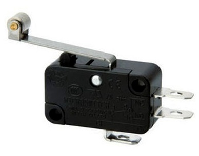
Tumblr. You don't need just any toggle switch. It must satisfy several conditions. Firstly, it must be “double”. Those. service not one circuit line, but two. This is the kind of toggle switch you need, with six contacts:

Secondly, the toggle switch must be “soft”. Those. Switching it should not require much effort. Microswitches that are common today, as in the photo, fully satisfy this condition. Of course, in principle, nothing prevents you from using a hefty “trolleybus” toggle switch the size of a matchbox. Only it will require a much more powerful motor and gearbox, which will not be so easy to find. For a microswitch, almost any servo drive is suitable, of which there are plenty in stores with spare parts for radio-controlled models.
"Fin". This element was added at the very end of the idea. Initially it was not on the diagram. It just seemed to me that the lever did not lift the lid high enough. To increase... mmm... expressiveness For the whole action, it is necessary that the lid rises more... clearly. Of course, in theory, this “fin” would have to be immediately embedded in the profile of the lever so that they would be a single whole. But the idea to add it came to me when almost the entire structure was already assembled. Therefore, the “fin” became a separate element glued to the lever.
Lever arm. Thick plexiglass plate. Tough enough to confidently throw the toggle switch (step 3). The main problem is to correctly and accurately develop its profile. It should turn freely without catching anything along the way, lift the lid and exactly rest against the click of the toggle switch.
Battery. Initially, I was planning on using a regular nine-volt. It is also shown in the diagram. However, it later turned out that for the found motor with a gearbox, nine volts was too much. The device worked very quickly. The lever popped out like an ejector blade, almost imperceptibly to the eye. At the same time, although the device worked as intended, at such a speed it was not possible to fully enjoy the uselessness of its work. Having replaced the nine-volt with two one and a half AA (I got a total of three volts), I greatly slowed down the operation of the mechanism and everything became as it should - smoothly and conceptually :-)
Motor and gearbox.. Just a motor with just a gearbox. I selected it by rotation speed (as slow as possible), by the force created (preferably higher than calculated) and by price (as low as possible). As a result, according to all these conditions, such a motor with a gearbox was selected. Inexpensive, compact, suitable for voltage, gave low speeds and developed quite impressive force on the lever.

How did I calculate how much force I needed on the gearbox? Very simple. Although completely clumsy. I just took the electronic scales, took the toggle switch, leaned it with the clicker on the scale plate and pressed until it switched. At the moment of switching, I took readings from the scale display. Of course, the resulting value was not from the series “how many ounces per inch,” but “how many ounces per size of the scale plate,” but still this figure gave some general approximate idea. You could estimate the error... In my case, I needed to look for a motor with a gearbox that would give about 30 ounces per inch to the lever. Well, give or take... The selected mechanism produces 50 ounces per inch, which is quite enough with all the errors.
The diagram above is missing another important detail:
Reverse breaker. It is needed so that the lever, returning to its original position after switching the toggle switch (step 4), cuts off the entire system and does not move anymore (step 5). It seemed to me that such a breaker was such a primitive, obvious and simple thing:
... that it is completely unworthy of attention in the drawing. Oh, how wrong I was!!! In the entire project, this damn breaker became the biggest adventure that really spoiled my nerves!
The electrical circuit of the device looks like this:

S1 is the main “double” toggle switch. The essence of its operation is that it simply switches the polarity of the current supplied to the motor (M). Accordingly, depending on the position of the switch, the drive rotates either clockwise or counterclockwise.
S2 is the same reverse breaker that should open the circuit when the lever takes its original position after switching toggle switch S1 to reverse.
This was all the theoretical part. Now - from theory to action.
The problems started from the very first moment. The store I linked to above did not have the required gearboxes in stock. They swore that they would purchase a new batch within a week and send it to me right away. They apologized terribly and offered to replace it with another gearbox. But it was complete with all sorts of gears, fasteners that I didn’t need, and in general, it looked like it was some kind of helicopter kit that didn’t suit me for the price. On eBay, the same gearboxes cost twice as much for some reason. In other stores, nothing suitable was found right away either... I had some time reserve and I could wait. According to my estimates, collecting all this will take a couple of evenings. Plus a couple of days for postage. A day in reserve just in case. So, if they send it to me at least five days before “hour X,” then I will have time to make the gift on time. Well, if they don’t send it, there’s nothing to do - I’ll get it on eBay with express delivery... But the store did not disappoint. The gearbox was sent on time.
First of all, it was necessary to carry out an experiment with a lever and a toggle switch. After all, if I missed the calculations, then the gearbox will not have enough strength to switch the toggle switch, which means that another gearbox with different dimensions is needed and all other calculations will also become different. Before sawing out the lever and making a box, you need to make sure that the device is theoretically operable.
The first stage of the experiment is to check the electrical circuit. According to the multimeter readings, the toggle switch successfully changed the output polarity:
The second stage of the experiment is to connect a gearbox with a lever and see if it will switch the toggle switch. As a lever I used some piece of plexiglass, the first one that came to my hand:

If everything is done correctly, then the motor should swing the lever back and forth, switching the toggle switch from one side to the other:
OK. The experiment was a complete success and it was possible to assemble the final device based on this gearbox.
As I already said, I started making his day box from plywood:

The only subtlety here was with the connection of the planes. If they are overlapped, the ends of the sheets will be visible. It's not beautiful. Therefore, the edges of all plates were filed at 45°:

Now they can be glued so that the ends at the joints are not visible:

To fix the gearbox in the box, I bent this scary bracket from an old slot plug:

It seemed so scary to me that I decided to paint it. For aesthetics... I’m not sure, however, that painting brought this very aestheticism to the product:

Hmmm... It's a rare case when something looks even more disgusting in a photograph than in reality. Usually it happens the other way around :-)
Lever... First, the printed template was transferred to a piece of plexiglass:

Here I had to be very, very precise. The device, although simple, allowed only very small errors. Otherwise, either it won’t get into the toggle switch, or it will start to catch on the box... I even tucked a fresh, sharp blade into the jigsaw for this occasion:

In the end, everything worked out as it should have:

Unfortunately, in our imperfect Universe, there is such a phenomenon - inertia. In my case, this meant that even after cutting off the power to the motor, it still continued to swing the lever by inertia before stopping completely.
The creators of this gearbox, apparently, also suspected the existence of inertia. Therefore, they provided some kind of fuse in the gear mechanism. If the lever rests on something, and the gears still continue to rotate, then so that the entire gearbox does not blow apart (after all, it is plastic), they made a switch there. When pressed, the lever switches to reverse. Not for long.
In the end, I got it like this: the lever goes to rollback, opens the breaker, the current on the motor is turned off, the lever continues to press further by inertia, the fuse in the gearbox trips, the lever goes in the other direction... the breaker, the stump is clear, restores the circuit again, the motor turns on , the lever again goes to the breaker, it opens... inertia, rollback, contact... and so it hammers the tap dance to the point of numbness. It looks funny, of course, but...
It would seem that the breaker needs to be adjusted so that it breaks the chain a little in advance, taking into account the subsequent inertia of the lever. In reality, making this amendment turned out to be extremely difficult. There were always two extremes: either the current was cut off too early and the lever did not lower all the way (and therefore the lid of the box did not close), or the break was triggered too late and the mechanism fell into the “tap dance” that I described above.
There are a lot of factors that immediately come together. Including the length of the breaker lever. I even made my own tiny breaker from a micro mouse button. It still didn't work. And I tried to make a breaker in the form of two copper strips, like in a relay... I tried everything. I almost went crazy trying to set everything up the way it should! It turned out that we had to make some kind of very precise trimming mechanism with microfeed. So that the interrupt delay can be adjusted with micron precision...
Fortunately, there was an easier way. It was enough to just think outside the box and... completely abandon this type of breaker. Who said that contact can only be interrupted by a lever design? There are a million ways to solve it mechanically, without using a lever (electronic methods are not considered in this case).
The lever is secured to the gearbox by a large, beautiful metal washer. So, you can use it directly as one of the contacts. A second contact tendril will crawl along it. Opening is carried out simply by depriving the antenna of contact with the washer. With simple tape. Like this:

The adjustment is made as follows: first, the insulating tape is glued with a large margin, and then, with a scalpel, tiny strips the thickness of a hair are cut from it, until the lever begins to stop exactly where it is needed.
And no complex designs with microfeeding and everything else:

Anticipating the obvious question - no, the “tendril” will not be wiped off by the tape. I mean, sooner or later he will wipe it, of course - eternal materials do not exist in the world. But I polished it at the point of contact, and it doesn’t press so hard. I then applied the tape in two layers. In general, it will take many years to wear out. The solution is quite acceptable and works like a charm:
In the video above, I still switch the main toggle switch manually. But the reverse cut-off already occurs on its own, using a breaker made of a washer and tape.
The reliability of the design was confirmed by a fact that was not very pleasant for me... I don’t know how and how, but when the package with the device arrived at the recipient, it turned out that that screw that secures the washer to the gearbox axis fell out! I can’t imagine what they did with the parcel at the post office. But even with this axial screw falling out, the box continued to work perfectly... I instructed the recipient over the phone how to return this screw to its place. I hope he can handle this kind of repair. But an unpleasant defect has surfaced, yes... :-(
By that time, the remaining parts of the box were glued together and ready. I did not glue the bottom of the box, to which the gearbox and battery pack are attached, to the walls. It turned out to be sufficient to secure it with decorative metal corners:

If you carefully dig out two nails in each corner, the bottom will freely separate from the rest of the structure.
Hinges for the lid in style:

Now, somewhere here I realized that it would be nice to increase the amount of lifting of the lid during the release of the lever. I drew, sawed out and glued a “fin” onto the lever, which this rise increases to the desired height:

A little more decor and the device is completely ready:

In action.


