Diagram for switching on fluorescent lamps without starters. We connect the burnt out fluorescent lamp. Operating principle of the epra
Despite the emergence of more “advanced” LED lamps, daylighting devices continue to be in demand due to their affordable price. But there's a catch: you can't just plug them in and light them without adding a couple of extra elements. Electrical diagram connecting fluorescent lamps, which includes these parts, is quite simple and serves to start the lamps of this type. You can easily assemble it yourself after reading our material.
Design and operating features of the lamp
The question arises: why do you need to assemble some kind of circuit to turn on such light bulbs? To answer it, it is worth analyzing their operating principle. So, fluorescent (otherwise known as gas-discharge) lamps consist of the following elements:
- A glass flask whose walls are coated on the inside with a phosphorus-based substance. This layer emits a uniform white glow when exposed to ultraviolet radiation and is called a phosphor.
- On the sides of the flask there are sealed end caps with two electrodes each. Inside, the contacts are connected by a tungsten filament coated with a special protective paste.
- The daylight source is filled with an inert gas mixed with mercury vapor.
Reference. Glass flasks can be straight or curved in the shape of a Latin “U”. The bend is made in order to group the connected contacts on one side and thus achieve greater compactness (an example is the widely used housekeeper light bulbs).
The glow of the phosphor is caused by a flow of electrons passing through mercury vapor in an argon environment. But first, a stable glow discharge must arise between the two filaments. This requires a short-term high voltage pulse (up to 600 V). To create it when the lamp is turned on, the above-mentioned parts are needed, connected according to a certain circuit. The technical name of the device is ballast or ballast.

In housekeepers, the ballast is already built into the base
Traditional circuit with electromagnetic ballast
In this case, the key role is played by a coil with a core - a choke, which, thanks to the phenomenon of self-induction, is capable of providing a pulse of the required magnitude to create a glow discharge in a fluorescent lamp. How to connect it to power via a choke is shown in the diagram:

The second element of the ballast is the starter, which is a cylindrical box with a capacitor and a small neon light bulb inside. The latter is equipped with a bimetallic strip and acts as a circuit breaker. Connection via electromagnetic ballast works according to the following algorithm:
- After the main switch contacts close, the current passes through the inductor, the first filament of the lamp and the starter, and returns through the second tungsten filament.
- The bimetallic plate in the starter heats up and closes the circuit directly. The current increases, causing the tungsten filaments to heat up.
- After cooling, the plate returns to its original shape and opens the contacts again. At this moment, a high voltage pulse is formed in the inductor, causing a discharge in the lamp. Then, to maintain the glow, 220 V coming from the mains is enough.

This is what the starter filling looks like - only 2 parts
Reference. The principle of connection with a choke and a capacitor is similar to a car ignition system, where a powerful spark on the candles jumps when the high-voltage coil circuit breaks.
A capacitor installed in the starter and connected in parallel to the bimetallic breaker performs 2 functions: it prolongs the action of the high-voltage pulse and serves as protection against radio interference. If you need to connect 2 fluorescent lamps, then one coil will be enough, but you will need two starters, as shown in the diagram.

More details about the operation of gas-discharge light bulbs with ballasts are described in the video:
Electronic activation system
Electromagnetic ballast is gradually being replaced by new electronic system Electronic ballasts devoid of such disadvantages:
- long lamp startup (up to 3 seconds);
- crackling or clicking noises when turned on;
- unstable operation at air temperatures below +10 °C;
- low-frequency flickering, which has a detrimental effect on human vision (the so-called strobe effect).
Reference. The installation of daylight sources is prohibited on production equipment with rotating parts precisely because of the strobe effect. With such lighting, an optical illusion occurs: it seems to the worker that the machine spindle is motionless, but in fact it is spinning. Hence - industrial accidents.

The electronic ballast is a single block with contacts for connecting wires. Inside there is an electronic frequency converter board with a transformer, replacing the outdated electromagnetic type control gear. Connection diagrams for fluorescent lamps with electronic ballast are usually depicted on the unit body. Everything is simple here: on the terminals there are indications where to connect the phase, neutral and ground, as well as the wires from the lamp.
Starting light bulbs without a starter
This part of the electromagnetic ballast fails quite often, and there is not always a new one in stock. To continue to use the daylight source, you can replace the starter with a manual breaker - a button, as shown in the diagram:

The point is to manually simulate the operation of a bimetallic plate: first close the circuit, wait 3 seconds until the lamp filaments warm up, and then open it. Here it is important to choose the right button for 220 V voltage so that you do not get an electric shock (suitable for a regular doorbell).
During the operation of a fluorescent lamp, the coating of the tungsten filaments gradually crumbles, which is why they can burn. The phenomenon is characterized by blackening of the edge zones near the electrodes and indicates that the lamp will soon fail. But even with burnt-out spirals, the product remains operational, it just needs to be connected to the electrical network according to the following diagram:
![]()
If desired, a gas-discharge light source can be ignited without chokes and capacitors, using a ready-made mini-board from a burnt-out energy-saving light bulb, operating on the same principle. How to do this is shown in the following video.
We offer two options for connecting fluorescent lamps, without using a choke.
Option 1.
All fluorescent lamps, operating from an alternating current network (except for lamps with high-frequency converters), emit a pulsating (with a frequency of 100 pulsations per second) luminous flux. This has a tiring effect on people's vision and distorts the perception of rotating components in mechanisms.
The proposed lamp is assembled according to the well-known power supply circuit for a fluorescent lamp with rectified current, characterized by the introduction of a high-capacity capacitor of the K50-7 brand into it to smooth out ripples.
When you press the common key (see diagram 1), push-button switch 5B1 is activated, connecting the lamp to the mains, and button 5B2, which closes the filament circuit of the LD40 fluorescent lamp with its contacts. When the keys are released, switch 5B1 remains on, and button SB2 opens its contacts, and the lamp lights up from the resulting self-induction EMF. When the key is pressed a second time, switch SB1 opens its contacts and the lamp goes out.
I do not provide a description of the switching device because of its simplicity. To ensure uniform wear of the lamp filaments, the polarity of the lamp should be changed after approximately 6000 hours of operation. The light flux emitted by the lamp has virtually no pulsations.
Scheme 1. Connections of a fluorescent lamp with a burnt-out filament (option 1.)
In such a lamp you can even use lamps with one burnt-out filament. To do this, its terminals are closed on the base with a spring made of a thin steel string, and the lamp is inserted into the lamp so that the “plus” of the rectified voltage is supplied to the closed legs (the top thread in the diagram).
Instead of a KSO-12 capacitor of 10,000 pF, 1000 V, a capacitor from a failed starter for LDS can be used.
Option 2.
The main reason for the failure of fluorescent lamps is the same as for incandescent lamps - burnout of the filament. For a standard lamp, a fluorescent lamp with this kind of malfunction is, of course, unsuitable and has to be thrown away. Meanwhile, according to other parameters, the resource of a lamp with a burnt-out filament often remains far from exhausted.
One of the ways to “reanimate” fluorescent lamps is to use cold (instant) ignition. To do this, at least one of the cathodes must be
control emission activity (see diagram implementing this method).
The device is a diode-capacitor multiplier with a factor of 4 (see diagram 2). The load is a circuit of a gas-discharge lamp and an incandescent lamp connected in series. Their powers are the same (40 W), the rated supply voltages are also close in value (103 and 127 V, respectively). Initially, when an alternating voltage of 220 V is supplied, the device operates as a multiplier. As a result, it turns out that applied to the lamp high voltage, which ensures “cold” ignition.

Scheme 2. Another option for connecting a fluorescent lamp with a burnt-out filament.
After the occurrence of a stable glow discharge, the device switches to the mode of a full-wave rectifier loaded with active resistance. The effective voltage at the output of the bridge circuit is almost equal to the mains voltage. It is distributed between lamps E1.1 and E1.2. The incandescent lamp functions as a current-limiting resistor (ballast) and at the same time it is used as a lighting lamp, which increases the efficiency of the installation.
Note that a fluorescent lamp is actually a kind of powerful zener diode, so changes in the supply voltage affect mainly the glow (brightness) of the incandescent lamp. Therefore, when the network voltage is highly unstable, the E1_2 lamp must be taken with a power of 100 W at a voltage of 220 V.
The combined use of two different types of light sources, complementary to each other, leads to improved lighting characteristics: pulsations of the light flux are reduced, the spectral composition of the radiation is closer to natural.
The device does not exclude the possibility of being used as a ballast and a standard choke. It is connected in series at the input of the diode bridge, for example, in an open circuit instead of a fuse. When replacing D226 diodes with more powerful ones - the KD202 series or KD205 and KTs402 (KTs405) blocks, the multiplier allows you to power fluorescent lamps with a power of 65 and 80 W.
A correctly assembled device does not require adjustment. In case of unclear ignition of the glow discharge or in its absence at all at the rated mains voltage, the polarity of the fluorescent lamp connection should be changed. It is first necessary to select burnt-out lamps to determine the possibility of working in this lamp.
The switching circuit for fluorescent lamps is much more complex than that of incandescent lamps.
Their ignition requires the presence of special starting devices, and the life of the lamp depends on the quality of these devices.
To understand how launch systems work, you must first become familiar with the design of the lighting device itself.
A fluorescent lamp is a gas-discharge light source, the luminous flux of which is formed mainly due to the glow of a phosphor layer applied to the inner surface of the bulb.

When the lamp is turned on, an electronic discharge occurs in the mercury vapor that fills the test tube and the resulting UV radiation affects the phosphor coating. With all this, the frequencies of invisible UV radiation (185 and 253.7 nm) are converted into visible light radiation.
These lamps have low energy consumption and are very popular, especially in industrial premises.
Scheme
When connecting fluorescent lamps, a special starting and regulating technique is used - ballasts. There are 2 types of ballasts: electronic - electronic ballast (electronic ballast) and electromagnetic - electromagnetic ballast (starter and choke).
Connection diagram using electromagnetic ballast or electronic ballast (throttle and starter)
A more common connection diagram for a fluorescent lamp is using an electromagnetic amplifier. This starter circuit.
Operating principle: when the power supply is connected, a discharge appears in the starter and
the bimetallic electrodes are short-circuited, after which the current in the circuit of the electrodes and the starter is limited only by the internal resistance of the inductor, as a result of which the operating current in the lamp increases almost three times and the electrodes of the fluorescent lamp instantly heat up.
At the same time, the bimetallic contacts of the starter cool down and the circuit opens.
At the same time, the choke breaks, thanks to self-induction, creates a triggering high-voltage pulse (up to 1 kV), which leads to a discharge in the gas environment and the lamp lights up. After which the voltage on it will become equal to half of the mains voltage, which will not be enough to re-close the starter electrodes.
When the lamp is on, the starter will not participate in the operating circuit and its contacts will and will remain open.
Main disadvantages
- Compared to a circuit with electronic ballast, electricity consumption is 10-15% higher.
- Long start-up of at least 1 to 3 seconds (depending on lamp wear)
- Inoperability at low ambient temperatures. For example, in winter in an unheated garage.
- The stroboscopic result of a flashing lamp, which has a bad effect on vision, and the parts of machine tools rotating synchronously with the mains frequency appear motionless.
- The sound of the throttle plates humming, growing over time.

Switching diagram with two lamps but one choke. It should be noted that the inductance of the inductor must be sufficient for the power of these two lamps.
It should be noted that in a sequential circuit for connecting two lamps, 127 Volt starters are used; they will not work in a single-lamp circuit, which will require 220 Volt starters

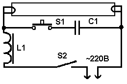
This circuit, where, as you can see, there is no starter or throttle, can be used if the filaments of the lamps have burned out. In this case, the LDS can be ignited using step-up transformer T1 and capacitor C1, which will limit the current flowing through the lamp from a 220-volt network.

This circuit is suitable for the same lamps whose filaments have burned out, but here there is no need for a step-up transformer, which clearly simplifies the design of the device

But such a circuit using a diode rectifier bridge eliminates the flickering of the lamp at the mains frequency, which becomes very noticeable as it ages.

or more difficult

If the starter in your lamp has failed or the lamp is constantly blinking (along with the starter if you look closely under the starter housing) and there is nothing at hand to replace it, you can light the lamp without it - enough for 1-2 seconds. short-circuit the starter contacts or install button S2 (caution of dangerous voltage)

the same case, but for a lamp with a burnt-out filament

Connection diagram using electronic ballast or electronic ballast
An electronic ballast (EPG), unlike an electromagnetic one, supplies the lamps with a high-frequency voltage from 25 to 133 kHz rather than the mains frequency. And this completely eliminates the possibility of lamp flickering noticeable to the eye. The electronic ballast uses a self-oscillator circuit, which includes a transformer and an output stage using transistors.
Fluorescent lamps (FLLs) are widely used to illuminate both large areas of public premises and as household light sources. The popularity of fluorescent lamps is largely due to their economic characteristics. Compared to incandescent lamps, this type of lamp has high efficiency, increased light output and a longer service life. However, a functional disadvantage of fluorescent lamps is the need for a starting starter or a special ballast (ballast). Accordingly, the task of starting the lamp when the starter fails or is absent is urgent and relevant.
The fundamental difference between an LDS and an incandescent lamp is that the conversion of electricity into light occurs due to the flow of current through mercury vapor mixed with an inert gas in a bulb. Current begins to flow after breakdown of the gas by high voltage applied to the electrodes of the lamp.
- Throttle.
- Lamp bulb.
- Luminescent layer.
- Starter contacts.
- Starter electrodes.
- Starter housing.
- Bimetallic plate.
- Lamp filaments.
- Ultraviolet radiation.
- Discharge current.
The resulting ultraviolet radiation lies in the part of the spectrum invisible to the human eye. To convert it into a visible light flux, the walls of the bulb are coated with a special layer, a phosphor. By changing the composition of this layer, you can obtain different light shades.
Before the direct launch of the LDS, the electrodes at its ends are heated by passing a current through them or due to the energy of a glow discharge.
High breakdown voltage is provided by ballasts, which can be assembled according to a well-known traditional circuit or have a more complex design.
Starter operating principle
In Fig. Figure 1 shows a typical connection of an LDS with a starter S and a choke L. K1, K2 – lamp electrodes; C1 is a cosine capacitor, C2 is a filter capacitor. A mandatory element of such circuits is a choke (inductor) and a starter (chopper). The latter is often used as a neon lamp with bimetallic plates. To improve the low power factor due to the presence of inductor inductance, an input capacitor is used (C1 in Fig. 1).

Rice. 1 Functional diagram of LDS connection
The LDS startup phases are as follows:
1) Warming up the lamp electrodes. In this phase, the current flows through the circuit “Network – L – K1 – S – K2 – Network”. In this mode, the starter begins to close/open randomly.
2) At the moment the circuit is broken by the starter S, the magnetic field energy accumulated in the inductor L is applied in the form of high voltage to the electrodes of the lamp. An electrical breakdown of the gas inside the lamp occurs.
3) In breakdown mode, the lamp resistance is lower than the resistance of the starter branch. Therefore, the current flows along the circuit “Network – L – K1 – K2 – Network”. In this phase, inductor L acts as a current-limiting reactor.
Disadvantages of the traditional LDS starting circuit: acoustic noise, flickering with a frequency of 100 Hz, increased start-up time, low efficiency.
Operating principle of electronic ballasts
Electronic ballasts (EPG) use the potential of modern power electronics and are more complex, but also more functional circuits. Such devices allow you to control the three startup phases and adjust the light output. The result is longer lamp life. Also, due to the lamp being powered with a current of a higher frequency (20÷100 kHz), there is no visible flicker. A simplified diagram of one of the popular electronic ballast topologies is shown in Fig. 2.

Rice. 2 Simplified circuit diagram of electronic ballasts
In Fig. 2 D1-D4 – mains voltage rectifier, C – filter capacitor, T1-T4 – transistor bridge inverter with transformer Tr. Optionally, the electronic ballast may contain an input filter, a power factor correction circuit, additional resonant chokes and capacitors.
A complete schematic diagram of one of the typical modern electronic ballasts is shown in Fig. 3.

Rice. 3 Diagram of BIGLUZ electronic ballasts
The circuit (Fig. 3) contains the main elements mentioned above: a bridge diode rectifier, a filter capacitor in the DC link (C4), an inverter in the form of two transistors with wiring (Q1, R5, R1) and (Q2, R2, R3), inductor L1, transformer with three terminals TR1, trigger circuit and lamp resonant circuit. Two windings of the transformer are used to turn on transistors, the third winding is part of the resonant circuit of the LDS.
Methods for starting LDS without specialized ballasts
When a fluorescent lamp fails, there are two possible reasons:
1) . In this case, it is enough to replace the starter. The same operation should be carried out if the lamp flickers. In this case, upon visual inspection, there are no characteristic darkening on the LDS flask.
2) . Perhaps one of the electrode threads has burned out. Upon visual inspection, darkening may be noticeable at the ends of the bulb. Here you can use known starting circuits to continue operating the lamp even with burnt-out electrode threads.
For emergency starting, a fluorescent lamp can be connected without a starter according to the diagram below (Fig. 4). Here the user plays the role of starter. Contact S1 is closed for the entire period of lamp operation. Button S2 is closed for 1-2 seconds to light the lamp. When S2 opens, the voltage on it at the moment of ignition will be significantly higher than the mains voltage! Therefore, extreme caution should be exercised when working with such a scheme.

Rice. 4 Schematic diagram starting the LDS without a starter
If you need to quickly ignite an LVDS with burnt filaments, then you need to assemble a circuit (Fig. 5).
Rice. 5 Schematic diagram of connecting an LDS with a burnt filament
For a 7-11 W inductor and a 20 W lamp, the C1 rating is 1 µF with a voltage of 630 V. Capacitors with a lower rating should not be used.
Automatic circuits for starting an LDS without a choke involve using an ordinary incandescent lamp as a current limiter. Such circuits, as a rule, are multipliers and supply the LDS with direct current, which causes accelerated wear of one of the electrodes. However, we emphasize that such circuits allow you to run even an LDS with burnt-out electrode threads for some time. A typical connection diagram for a fluorescent lamp without a choke is shown in Fig. 6.

Rice. 6. Block diagram of connecting an LDS without a choke

Rice. 7 Voltage on the LDS connected according to the diagram (Fig. 6) before start-up
As we see in Fig. 7, the voltage on the lamp at the moment of starting reaches the level of 700 V in approximately 25 ms. Instead of an HL1 incandescent lamp, you can use a choke. Capacitors in the diagram of Fig. 6 should be selected within 1÷20 µF with a voltage of at least 1000V. Diodes must be designed for a reverse voltage of 1000V and a current of 0.5 to 10 A, depending on the lamp power. For a 40 W lamp, diodes rated for current 1 will be sufficient.
Another version of the launch scheme is shown in Fig. 8.

Rice. 8 Schematic diagram of a multiplier with two diodes
Parameters of capacitors and diodes in the circuit in Fig. 8 are similar to the diagram in Fig. 6.
One of the options for using a low-voltage power supply is shown in Fig. 9. Based on this diagram (Fig. 9), you can assemble wireless lamp daylight on battery.

Rice. 9 Schematic diagram of connecting LDS from a low-voltage power source
For the above circuit, it is necessary to wind a transformer with three windings on one core (ring). As a rule, the primary winding is wound first, then the main secondary (indicated as III in the diagram). Cooling must be provided for the transistor.
Conclusion
If the fluorescent lamp starter fails, you can use an emergency “manual” start or simple circuits DC power supply. When using circuits based on voltage multipliers, it is possible to start a lamp without a choke using an incandescent lamp. Working for DC, there is no flicker and noise of the LDS, but the service life is reduced.
If one or two filaments of the cathodes of a fluorescent lamp burn out, it can continue to be used for some time, using the above-mentioned circuits with increased voltage.
Well of course about " eternal lamp"This is a loud word, but here's how to "revive" a fluorescent lamp with burnt-out filaments quite possible...
In general, everyone has probably already understood that we are not talking about an ordinary incandescent light bulb, but about gas-discharge light bulbs (as they were previously called “fluorescent lamps”), which looks like this:
The operating principle of such a lamp: due to a high-voltage discharge, a gas (usually argon mixed with mercury vapor) begins to glow inside the lamp. In order to light such a lamp, a fairly high voltage is required, which is obtained through a special converter (ballast) located inside the housing.
useful links for general development : self-repair of energy-saving lamps, energy-saving lamps - advantages and disadvantages
The standard fluorescent lamps used are not without drawbacks: during their operation, the buzzing of the choke can be heard, the power system has a starter that is unreliable in operation, and most importantly, the lamp has a filament that can burn out, which is why the lamp has to be replaced with a new one.
But there is also Alternative option: the gas in the lamp can be ignited even with broken filaments - to do this, simply increase the voltage at the terminals.
Moreover, this use case also has its advantages: the lamp lights up almost instantly, there is no buzzing during operation, and a starter is not needed.
To light a fluorescent lamp with broken filaments (by the way, not necessarily with broken filaments...), we need a small circuit:

Capacitors C1, C4 must be paper, with an operating voltage of 1.5 times the supply voltage. Capacitors C2, SZ should preferably be mica. Resistor R1 must be wirewound, according to the lamp power indicated in the table
|
Power lamps, W |
C1 -C4 µF |
C2 - NW pF |
D1 - D4 |
Ohm |
|
3300 |
D226B |
|||
|
6800 |
D226B |
|||
|
6800 |
D205 |
|||
|
6800 |
D231 |
Diodes D2, DZ and capacitors C1, C4 represent a full-wave rectifier with doubling the voltage. The values of capacitances C1, C4 determine the operating voltage of lamp L1 (the larger the capacitance, the greater the voltage on the electrodes of lamp L1). At the moment of switching on, the voltage at points a and b reaches 600 V, which is applied to the electrodes of lamp L1. At the moment of ignition of lamp L1, the voltage at points a and b decreases and provides normal operation lamp L1, designed for voltage 220 V.
The use of diodes D1, D4 and capacitors C2, SZ increases the voltage to 900 V, which ensures reliable ignition of the lamp at the moment of switching on. Capacitors C2, SZ simultaneously help suppress radio interference.
Lamp L1 can work without D1, D4, C2, C3, but in this case the reliability of inclusion decreases.
Data for circuit elements depending on the power of fluorescent lamps are given in the table.


