AVR microcontroller programmers. Simple programmers. Making an LPT programmer for AVR microcontrollers Program for a 74hc374 programmer for lpt
One of the simplest AVR programmers is the LPT port programmer. This is due to the fact that the signal levels of the LPT port are compatible with the signal levels necessary for programming the ATS. Therefore, signals from the LPT port can be directly supplied to the microcontroller (resistors are only needed to protect the port from accidental short circuits). Such a programmer can be assembled from scrap materials in literally 5 minutes!
As you can see, the LPT programmer circuit for AVR is extremely simple:

To make an LPT programmer we will need:

You can use any resistors you find in the range from 100 to 150 Ohms. You can assemble the programmer without resistors at all, but then it will be even easier to burn the port. You can use an IDE cable as a cable. When connecting a loop, for more stable operation of the programmer, each “signal” wire must alternate with a “ground” wire. This will reduce the level of interference induced in the lines and thereby increase the length of the programming wire. The length of the cable should be within 50 cm. You also need a connector for connecting to the programmable device.
For in-circuit programming, Atmel recommends the following standard connectors:

If you plan to get serious about microcontrollers, make the connectors standard. For one-time programming of the device, I recommend using the programmer (such connectors connect the buttons and LEDs of the computer case to the motherboard) and the PLS male pins on the board. This makes it possible to simplify the layout of the device board as much as possible, since the pins for the programmer are installed in close proximity to the microcontroller legs. The MOSI, MISO, SCK legs of AVR microcontrollers are always located together, so a triple connector can be used for them. We make separate connections for “ground” - GND and “reset” - Reset.
Assembling an LPT programmer in 5 steps:

Jumpers between connector pins 2-12 and 3-11 are needed so that our programmer is visible to programs like the STK200/300 programmer (STK200/300 is a kind of standard and therefore our programmer will be visible to many programs).
In order for our LPT programmer to work needed, to which we will connect the programmer for the microcontroller.
General recommendations:
— The LPT port is quite delicate - it is very easy to “shoot”, so be careful when working with the port.
— I would recommend making a separate connection for ground in all programmers. This is necessary so that the ground can be connected first and equalize the ground potentials of the programmable device and the computer. (For those who don’t know, if your computer is plugged into a regular outlet without a grounding contact, then due to the peculiarities of the computer power supply filter, there is always a potential of 110V on the computer case. If the programmer is “successfully” connected, this is quite enough to burn microcontroller or LPT port of a computer.
Conclusion:
-If you have decided to assemble your first programmer and your computer has an LPT port, then the “5 wires” programmer is the best option! It is extremely simple and will not be difficult to repeat. In addition, the programmer is compatible with classic STK200/300 programmers, which means it will be supported by many AVR programming programs.
-If you plan to program quite often, in order to secure the LPT port, I recommend assembling an LPT programmer with buffer elements (a good version of an LPT programmer can be found at izielectronics) or assembling an equally simple one ( COM port much more durable and more difficult to burn).
(Visited 66,795 times, 2 visits today)
Quite often, many people come across an interesting design on the Internet, but one thing holds it back - it is made using a controller. And it's so difficult...
In fact, everything is much simpler. If it is possible to purchase a controller, half the work is already done. All that remains is to “iron” the board, etch and solder it with parts... And now it comes to the controller. How to “revive” him? How to "flash"? The painful search for the programmer circuit and program begins. The circuit was found, but bad luck - on the back wall of the computer there are already 8 USB connectors, a port for a printer and not a single COM port for which the circuit was found.
There is another option for the development of events. There is a COM port on the computer. But for some reason the programmer refuses to “seam” the controller - an error constantly pops up. But the fact is that often on modern motherboards(and especially in laptops) COM ports are made very low in current. Because of this, the programming process ends before it even begins. In all the above cases, this simple diagram will help you.
This is a programmer for the LPT port. Despite all the apparent complexity, the scheme is quite simple and starts working immediately, without requiring any configuration. The parts are available and cost literally pennies. But the possibilities... With this device you can easily flash the controller not only in the socket, but also in-circuit (this applies to devices whose board is wired for an SMD controller case, but you don’t want to buy a socket for $20 for it).
Once assembled it looks like this:

This programmer with minor differences has been roaming the Internet for about 20 years. It is known as Clasic Tait Programer, ProPIC2, meProg. It is still produced by some companies and sold successfully.

The latest versions of the software can be downloaded from here:
- http://www.winpic800.com/
- http://melabs.com/support/progsoft.htm
- http://members.aon.at/electronics/pic/picpgm/
Here are the settings for WinPIC800:

And here is an adapter for flashing 8-14-18-20 output controllers.

| This diagram is also often viewed: |
For beginners, the question is “what are we going to use to flash our controller with?” gets up almost immediately. This problem can be solved in two ways - we buy a serial programmer or build our own. Naturally, it is not advisable to purchase any of the serial programmers at the initial stage of getting to know microcontrollers. The most simple solution there will be a so-called “five wires” programmer. This option is quite suitable for one-time use, but there is a great danger that sooner or later your LPT port on the computer will burn out. As a low-cost and safe option for a parallel port programmer, we use a more advanced circuit.
Introducing a simple and secure parallel port programmer. The programmer circuit is quite common in various variations and is based on the use of a 74HC 244N buffer chip. The buffer keeps your printer port safe and sound. Additionally, a resistor is included in the circuit, the purpose of which is to protect against static electricity.
The programmer is compatible with Atmel STK 200/300 and is supported by many popular compilers. The entire small set of parts for its assembly is quite common and will not cause any difficulties in purchasing. Printed circuit board made in a one-sided version with several jumpers.

To connect the programmer to a computer, it is convenient to use an LPT port extension cable.


Scheme in sPlan format 6.0 and board layout in format Sprint Layout You can download 4.0 under LUT below.
Let's find out what an ISP interface is and look at an inexpensive and convenient USB ISP programmer. Let's look at the schematic diagrams of the simplest programmers for AVR microcontrollers using COM and LPT ports of the computer. This information is quite enough to flash most models of AVR microcontrollers not only in Linux, but also in other OSes.
ISP In-System Programming Interface
In order to write a program to the AVR microcontroller you will need a programmer.
Programmer- it's small electronic circuit, which allows you to connect the microcontroller to one of the computer ports (COM, LPT, USB) for subsequent reading and writing of the firmware (programming).
There are quite a lot of different designs of programmers for AVR microcontrollers that connect to different computer ports.
The most reliable and convenient option is a programmer that connects to a USB port, since in new desktop computers and laptops no longer have COM and LPT ports installed.
In finished devices, the programmer is connected to the microcontroller via an interface ISP(In System Programming) - in-system programming interface. The ISP interface consists of several conductors through which a clock signal and data are received to connect the programmer with the microcontroller.
As a rule, the ISP interface is placed on boards in the form of ten or six pins, to which the programmer is connected via a suitable connector via a cable.
Rice. 4. ISP interface on the board.
Purpose of pins in the ISP interface:
- VCC - power supply plus, usually +5V;
- GND - power minus, ground (Ground);
- MOSI - data input (Master Out Slave In);
- MISO - data output (Master In Slave Out);
- SCK - clock signal (Serial Clock);
- RST - to provide a reset signal.
For in-circuit programming of the microcontroller, only 4 pins are sufficient, since the microcontroller can be powered from the circuit itself where it is installed.
How to connect the programmer to the AVR microcontroller chip if it is not soldered into the circuit? - very simply, using the same pins of the ISP interface, if necessary, powering the microcontroller from the power source.
USB ISP ASP programmer
To work with AVR chips, I purchased an inexpensive USB ISP programmer for about $10. Such a device is now on sale in many domestic and foreign online stores, so there should be no problems with the purchase.

Rice. 5. USB ISP - programmer with a cable for in-circuit programming of AVR microcontrollers from ATMEL.
This programmer is safe to use, small in size and supported by most programs for flashing AVR microcontrollers. USB ISP works under operating systems Linux, Mac OS X and Windows. For Linux, you do not need to install any drivers, after connecting the programmer to USB port The device will immediately be detected and ready for use.
Below I will give the pinout of the connectors of the USB ISP programmer - it will be useful to us later when connecting to the microcontroller.

Rice. 6. Location of pins on USB connector ISP (pinout).

Rice. 7. Location of contacts in the connector sockets connected to the USB ISP programmer.
What to do if you can’t buy a USB ISP programmer?- you can program microcontrollers using simple homemade programmers that connect to a COM or LPT port, but it is better to make a USB ISP yourself and program the microcontroller chip for it once with a simple homemade programmer via a COM or LPT port.

Rice. 8. Schematic diagram homemade USB ASP ISP programmer.
Detailed information on the manufacture of USB ASP, as well as printed circuit boards, drivers and firmware for the microcontroller can be found on the official website: http://www.fischl.de/usbasp/
In addition, there are quite a lot of resources on this free programmer on the Internet, there are many ready-made printed circuit board layouts, including in the SprintLayout program, so we will not dwell on this in detail in this article.
Programmer using COM port
This programmer is also called the “Gromov programmer”, in honor of the one who came up with this scheme, the creator of the Algorithm Builder program (a graphical environment for programming AVR under Windows using an algorithmic language) - G.L. Gromova.
This programmer allows you to program AVR chips using the COM port of the computer - RS232 interface. To assemble such a programmer, you will need a minimum of parts - 3 diodes, 7 resistors, a DB-9 or DB-25 connector (depending on which mating connector is installed in your computer) and an ISP connector for connecting to the microcontroller (or just a few conductors to chip). Any low-power diodes can be used in the circuit.

Rice. 9. Schematic diagram of the AVR microcontroller programmer via a computer COM port.
For completeness of information, below I will provide the pinout of the RS-232 ports for the DB-9 and DB-25 options.

Rice. 10. RS232 - COM Port, DB-9 pin layout.

Rice. 11. RS232 COM Port DB-25 - location of pins on connectors.
Programmer using LPT port
As we know, the LPT port of a computer is designed to connect a local printer (Local Printer Port), but nevertheless it is often used to connect various devices and homemade products. In this case, we can use it to program AVR microcontrollers, having assembled very simple diagram which is given below.
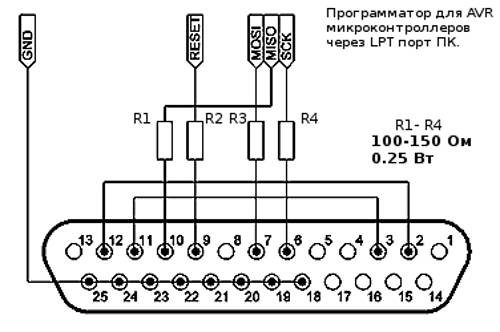
Rice. 12. Schematic diagram of a programmer for AVR microcontrollers using the LPT port of a computer.
As you can see, the circuit is even simpler than in version with, here we only need 4 low-power resistors and a connector (male, with pins) for connecting to the LPT port of the computer.

Rice. 13. Location of pins for LPT port connectors.
All parts and connections can be placed in the LPT connector housing, and to connect to the microcontroller, a cable with a connector for the ISP interface or simply the necessary conductors for connecting to the microchip can be brought out.
Software and Notes
Having connected the COM or LPT programmer to the microcontroller, you must remember to supply power to the microchip itself. You can use batteries or a power supply with a stabilizer as a power source for the microcontroller; this will be the safest for both the computer port and the chip. We have already discussed how to use it.
Under Linux there is a very powerful program that can work with USB ASP, COM and LPT programmers - this program AVRDUDE, it will be discussed in the following sections.
To flash AVR chips under Windows using COM data and LPT programmers need the UniProf program from Nikolaev, which is a universal programmer for AVR (avr.nikolaew.org).
ATTENTION! Be extremely careful and careful when assembling and using programmers using the COM or LPT port of a computer, a simple mistake can easily set fire to these ports. For normal operation For such programmers, you should try to use the shortest possible wires from the connector to the programmer circuit and microcontroller. It is advisable for the computer microprocessor to have a frequency of no more than 1-2 GHz, and it is advisable to use Win2000 or WinXP as the OS for programming the chips.
It is also important to know that USB-RS232 (USB-COM Port) adapters most likely will not work with Gromov’s programmer; only those with newer chips will work, so it’s better to look for a machine with a native COM port.
Conclusion
The programmers discussed in the article are just a few of the most affordable and simple solutions from a large list of AVR programmers: USBTinyISP, AVR-Doper, AVR vusbtiny, AVRISP-MkII, FTDI programmers and others.
Now, in any case, you can assemble a programmer available to you and flash at least one chip, on the basis of which you can assemble another more convenient programmer or some other device.
In the next article we will figure out how to connect different models AVR microcontrollers to the programmer, find out where to get information about the pinout of microcontrollers.
For beginners, the question is “what are we going to use to flash our controller with?” gets up almost immediately. This problem can be solved in two ways - we buy a serial programmer or build our own. Naturally, it is not advisable to purchase any of the serial programmers at the initial stage of getting to know microcontrollers. The simplest solution would be the so-called “five wires” programmer. This option is quite suitable for one-time use, but there is a great danger that sooner or later your LPT port on the computer will burn out. As a low-cost and safe option for a parallel port programmer, we use a more advanced circuit.
Introducing a simple and secure parallel port programmer. The programmer circuit is quite common in various variations and is based on the use of a 74HC 244N buffer chip. The buffer keeps your printer port safe and sound. Additionally, a resistor is included in the circuit, the purpose of which is to protect against static electricity.
The programmer is compatible with Atmel STK 200/300 and is supported by many popular compilers. The entire small set of parts for its assembly is quite common and will not cause any difficulties in purchasing. The printed circuit board is made in a single-sided version with several jumpers.
To connect the programmer to a computer, it is convenient to use an LPT port extension cable.
Scheme in sPlan format 6.0 and board layout in format Sprint Layout You can download 4.0 under LUT below.


