Dial meter for eps capacitors. Eps oxide capacitor meter. Selecting a frequency for measuring ESR
To search for such capacitors, a device developed and manufactured by the author is proposed, which has high accuracy and resolution. For greater ease of use of the device, it is possible to use it together with almost any digital voltmeter (multimeter). Considering the affordable prices for “popular” digital multimeters of the 8300 series, the proposed design is a kind of “godsend” for many radio amateurs, especially considering that the circuit does not contain any scarce or expensive components or even motor units.
Oxide (electrolytic) capacitors are used everywhere. They affect the reliability and quality of operation of radio electronic equipment (RES). In terms of quality and purpose, capacitors are characterized by many indicators. First, the performance and scope of capacitors were assessed by capacitance, operating voltage, leakage current and weight and size indicators. The powers at which electrolytic capacitors are used have increased and the frequencies at which electrolytic capacitors are used have increased. Modern switching power supplies for electronic devices have a power of tens to hundreds of watts (or more) and operate at frequencies of tens to hundreds of kilohertz. The currents flowing through capacitors have increased, and accordingly, the requirements for their parameters have also increased.
Unfortunately, during mass production, quality indicators do not always meet standards. First of all, this affects such a parameter as equivalent series resistance (ESR), or ESR. This issue has received insufficient attention, especially in amateur radio literature, although the number of faults arising due to the fault of EPS capacitors is increasing. It’s a shame, but even among brand new capacitors, specimens with increased ESR are becoming increasingly common.
Foreign capacitors are also no exception. As measurements have shown, the ESR value of capacitors of the same type can differ several times. Having an ESR meter at your disposal, you can select capacitors with the lowest ESR value for installation in the most critical components of devices.
We should not forget that electrochemical processes take place inside the capacitor, which destroy the contacts in the area where the plates are connected to the aluminum contacts. If the ESR value of a new capacitor is overestimated, then its operation does not contribute to its reduction. On the contrary, EPS increases over time. As a rule, the more ESR the capacitor had before installation, the sooner its value will increase. The ESR of a faulty capacitor can increase from several ohms to several tens of ohms, which is equivalent to the appearance of a new element - a resistor inside the faulty capacitor. Since thermal power is dissipated on this resistor, the capacitor heats up, and in the contact zone, electrochemical processes proceed faster, promoting further growth of ESR.
Specialists in the repair of various electronic devices are well aware of the defects of switching power supplies associated with an increase in the ESR of capacitors. Measuring capacitance using widely used instruments often does not give the desired results. Unfortunately, such devices (C-meters) cannot detect capacitors that are defective in terms of ESR. The capacity will be within normal limits or only slightly underestimated. When the ESR value does not exceed 10 ohms, the readings of the capacitance meter do not give grounds for suspicion (this ESR value has practically no effect on the accuracy of measurements), and the capacitor is considered to be in good condition.
Technical requirements for the ESR meter. Increased demands on the quality of capacitors are primarily imposed in switching power supplies, where such capacitors are used as filters at frequencies up to 100 kHz or in switching circuits of power elements. The ability to measure ESR allows not only to identify failed capacitors (except for cases of leakage and short circuit), but also, which is very important, to carry out early diagnosis of ESR defects that have not yet appeared. To be able to measure ESR, the process of measuring the complex resistance of the capacitor is carried out at a sufficiently high frequency, where the capacitance is much less than the permissible ESR value. So, for example, for a capacitor with a capacity of 5 μF, the capacitance is 0.32 Ohms at a frequency of ) 00 kHz. As you can see, the capacitance of even a small-capacity electrolytic capacitor is many times less than the ESR of a defective capacitor. The ESR value of faulty capacitors with a capacity of up to 200 μF significantly exceeds 1 Ohm.
Based on the ESR value, you can confidently assess the suitability of a capacitor for certain purposes. When buying capacitors, you can use a portable ESR meter to select the best specimens. It is important that the process of measuring ESR can be carried out without dismantling the capacitors being tested. In this case, it is necessary that the capacitor is not shunted by a resistor having a resistance commensurate with the ESR. The maximum voltage on the probes of the device should be limited so as not to damage the elements of the RES being repaired. Semiconductor devices should not affect the readings of the ESR meter. This means that the voltage on the measured capacitor must be minimal in order to exclude the influence of the active elements of the RES.
When operating in stationary conditions, the device must be powered from the mains (you can, for example, use an appropriate switch and an external power supply). To prevent polarity reversal of an external power supply or charger, it is necessary to provide protection. To prevent deep discharge of batteries, it is necessary to use cut-off protection or at least provide an indication of battery voltage monitoring. To stabilize the device parameters, it is necessary to use a built-in voltage stabilizer. This stabilizer must satisfy at least two requirements: to be economical, i.e. have a low own current consumption, and provide a fairly stable output voltage when the input supply voltage changes in the range of at least 7... 10 V.
The EPS reading indicator is of great importance. ESR meters with discrete indication, for example, on LEDs, are of little use for rejecting (selecting) capacitors from large batches and have huge errors in ESR measurement. ESR meters with nonlinear scales cause problems with the implementation of a new scale, with reading the readings and have a large measurement error. New circuits on programmable “chips” (microcontrollers), sad to say, are not yet available to most radio amateurs. For the price of a microcontroller alone, you can purchase all the components for the manufacture of the ESR meter discussed below.
As part of the ESR meter, it is convenient to have a dial gauge with a linear scale that does not require any modifications, using, for example, one common scale 0...100 for all subranges of the device. When working with an ESR meter for a long time and intensively, it is very convenient to use a digital scale. However, independent production of a digital device is not profitable due to the complexity of the overall design and high cost. It is better to provide for the possibility of operating the meter in conjunction with a widely used and cheap digital multimeter of the 8300 series, for example the M830B. Any other digital voltmeter with similar characteristics, having a DC voltage measurement range of 0...200 mV or 0...2000 mV, is suitable. For the price of one microcontroller you can purchase one or even two such multimeters. The digital indicator of the ESR meter allows you to quickly sort capacitors. A dial (built-in) meter is useful in cases where there is no digital tester at hand.
Perhaps the most important parameter is the reliability of the device. And it, one way or another, depends on the human factor. What kind of device is this that fails if the capacitor being tested is not discharged? In a hurry, equipment repairmen often discharge capacitors not with resistors, but with wire jumpers, which has a detrimental effect on the service life of the electrolytic capacitors themselves. The device should not fail and discharge capacitors with extra currents.
The ESR meter must have a wide range of measurement of the ESR value. It is very good if it measures ESR from 10 Ohms to almost zero value. Measuring ESR of more than 10 Ohms is irrelevant, since electrolytic capacitors with such ESR are completely substandard, especially for working in pulse circuits, especially at frequencies of tens to hundreds of kilohertz. It is convenient to have a device that allows you to measure ESR values less than 1 ohm. In this case, an “exclusive” opportunity is provided to select the best examples of capacitors from among the best types with the highest capacity.
The main power source is a battery made up of nickel-cadmium disk batteries of type D-0.26D. They are more reliable and energy-intensive than 7D-0.1. It is possible to recharge the batteries.
Specifications
- Ranges of measured resistances......0...1 Ohm, 0...10 Ohm
- Frequency of measuring signal used.........77 kHz
- Supply voltage........7... 15 V
- Current consumption, no more......................4.5 mA
The circuit diagram of the ESR meter for electrolytic capacitors is shown in Fig. 1. The design of the device is based on an ohmmeter operating on alternating current. The frequency should not be increased to more than ] 00 kHz due to the upper limit frequency (100 kHz) of the K157DA1 type microcircuit detector, which is used in this device design; moreover, not all types of electrolytic capacitors are designed to operate at frequencies above 100 kHz.
The generator of the device is made on a DD1 microcircuit of type K561TL1. The choice of this type of IC is determined solely by considerations of increasing the efficiency of the device. In this situation, you can use other generators made on more common ICs, in particular on K561LA7 or K561LE5. This will increase the current consumption from the power source.
There are two requirements for the generator: amplitude stability and frequency stability. The first requirement is more important than the second, since a change in the amplitude of the generator output voltage is a greater destabilizing factor than a change in frequency. Therefore, there is no need to use quartz resonators, or to precisely set the frequency to exactly 77 kHz. The operating frequency of the device can be selected within the range of 60...90 kHz. Configuration and operation of the device must be carried out at the same operating frequency, since the stable parameters of the tuned device are maintained in a rather narrow frequency range.
From the output of the generator, a rectangular signal through elements R17-R19, C8 is supplied to the capacitor Cx being tested (terminals 1 and 2). From the capacitor Cx the signal goes to the amplifier, from the amplifier to the detector, then the rectified signal goes to the dial measuring device PA1 and a digital voltmeter (connector XS2). The flow of current through the capacitor under test causes a voltage drop across it. To measure low resistances, the detector needs high sensitivity, not to mention its linearity. If you significantly increase the current flowing through the capacitor under test, then the current consumed from the power source will also increase sharply.
In the author’s version, the current through the capacitor under test is approximately 1 mA, i.e. Each millivolt of voltage drop corresponds to 1 ohm of the EPS capacitor. With an ESR equal to 0.1 Ohm, it is necessary to deal with measuring voltages of 100 µV! Since this device is capable of measuring ESR values that are an order of magnitude smaller, we are talking about tens of microvolts, which must be clearly recorded by the meter.
Obviously, for the detector to work properly, the signal needs to be amplified. This task is performed by an amplifier stage: a low-noise transistor VT7 is used as an amplifier according to a circuit with an OE (the gain at the operating frequency is 20), a buffer amplifier is made on a transistor VT8, assembled according to a circuit with an OK.
Capacitor C9 is a high-pass filter element. The selected capacitance value of the capacitor SY actually prevents the operation of the R24C10 circuit at low frequencies. In such simple ways, a significant decrease in the frequency response in the low-frequency region is realized. The decrease in frequency response in the low-frequency region is additionally formed by the choice of capacitors C1 and C12 in the detector circuit. At HF, interference is additionally limited by resistor R23 (protective elements are also taken into account).
To ensure that the capacitor under test (undischarged) does not damage the generator IC, the circuit provides protective elements VD1, VD2, R19. A similar circuit, consisting of elements R22, VD3, VD4, protects the amplifier input. In operating mode (when measuring ESR), diodes have virtually no shunting effect on the signal. When the capacitor Cx under test is disconnected from terminals 1 and 2, the diodes limit the amplitude of the signal at the amplifier input, although a signal of this level does not lead to failure of the amplifier. This device protection scheme, despite its simplicity of implementation, has proven its high efficiency in practice.
The ESR meter for electrolytic capacitors is unpretentious in operation. The values of resistors R19 and R22 are selected in such a way as to ensure reliable discharge of the tested capacitors operating in almost any household equipment. Consequently, protective diodes must effectively discharge the capacitors under test, and at the same time be reliably protected from overcurrent when discharging the capacitors. Toggle switch section SA1.2 with button SA4 and resistors R20 and R21 are used to calibrate the device.
The most difficult thing was the choice of the detector circuit. There were specific problems here. Practical tests of many widely used diode detectors have only confirmed their unsuitability for linear voltage detection over a wide amplitude range. It was not possible to find anything suitable from a simple circuitry, implemented on discrete elements, that could be relied upon in the literature.
The very idea of using the K157DA1 microcircuit in the detector of the ESR meter arose by accident. I remembered that IC type K157DA1 was widely used in recording level indicators of various domestic tape recorders. First of all, my attention was attracted by the comparative simplicity of the circuit connection of this IC. The current consumed by the IC from the power supply was also satisfactory, as was the suitable operating frequency range. This IC can also operate with single-supply power. However, the typical inclusion of K157DA1 is not suitable in the case under consideration. As a result, it was necessary not only to modify the IC switching circuit in comparison with the standard one, but also to change the ratings of the trim elements several times.
This IC includes a two-channel full-wave rectifier. The second channel is not used in the design under consideration. Prototyping confirmed the linearity of IC detection at frequencies up to 100 kHz. Some ICs even had a certain margin in the upper limit frequency (two out of ten tested ICs were up to 140 kHz). A further increase in frequency caused a sharp decrease in the rectified voltage of the IC. The nonlinearity of IC detection manifested itself at minimal signal levels and with significant amplification of the IC. No less annoying was the output quiescent voltage (at pin 12 of the IC), which, according to reference data, can reach 50 mV, which was impossible to come to terms with if it was decided to make a measuring device and not an ESR indicator.
After some time, this problem was successfully overcome. Between pins 14 and 2 of the microcircuit, a resistor R3 with a resistance of 33 kOhm is installed in a typical connection. It is connected to the artificial midpoint of the voltage divider formed by resistors R1 and R2 (Fig. 1). This is an option for using ICs with unipolar power supply.
As it later turned out, the linearity of detection in the region of small amplitudes significantly depends on the value of the resistance of resistor R3. Reducing the resistance R3 several times ensures the necessary linearity of the detector, and, no less important, the resistance of this resistor also affects the value of the DC quiescent voltage (pin 12 of the IC). The presence of this voltage prevents normal measurements at low ESR values (you will have to perform a mathematical subtraction operation with each measurement). Hence the importance of setting the “zero” potential at the detector output.
The correct choice of resistor R3 practically eliminates this problem. In the proposed embodiment, the resistor resistance is more than three times less than the typical value. It makes sense to further reduce the value of this resistance, but at the same time the input resistance of the detector is also significantly reduced. It is now almost completely determined by the resistance of resistor R3.
Transistors VT1 and VT2 provide protection for the dial meter PA1. This inclusion of transistors provides a clear response threshold and does not shunt the PA1 head at all in the PA1 operating current range, which increases its reliability and increases its service life.
Switch SA3 serves for operational control of the battery voltage and allows you to measure it under load, i.e. directly during operation of the device. This is important because for many batteries over time, even with a deep discharge (without load), the voltage may be normal or close to the nominal one, but as soon as you connect a load, even a few milliamps, the voltage of such a battery drops sharply.
A micro-power voltage stabilizer (SV) is made on transistors VT3-VT6, which powers all elements of the device. When using an unstabilized power source, all device parameters change. Reducing the voltage (discharging) of the battery also significantly disrupts the entire setting. The detector, by the way, turned out to be the most resistant to changes in supply voltage. The most dependent on the supply voltage (the amplitude of the rectangular voltage changes greatly) is the generator, which makes operation of the device impossible.
The use of microcircuit SN causes irrational current consumption by the stabilizer itself, so it soon had to be abandoned. After experiments with various circuits using discrete elements, the author settled on the CH circuit shown in Fig. 1. In appearance, this SN is very simple, but its presence in this circuit is quite enough to ensure that all technical parameters of the ESR meter remain stable when the battery voltage changes from 7 to 10V. In this case, it is possible to power the device from an external power supply, even an unstabilized one, with a voltage of up to 15 V.
The MV's own energy consumption is determined by the value of the collector current of the transistor VT6 and was selected within the range of 100...300 μA. The VT6 transistor is an analogue of a low-power zener diode. Its voltage determines the value of the output voltage CH, which is less than the stabilization voltage of the zener diode by the value of the base-emitter junction voltage of transistor VT3.

Details. Resistors R1-R3, R5, R7, R15, R29 -10 kOhm, R4, R6, R8, R10, R11, R13, R24, R30-1 kOhm, R9-39 kOhm, R12-100 Ohm, R14-680 kOhm, R16 - 100 kOhm, R17, R25 - 2.4 kOhm, R18 - 4.7 kOhm, R19, R22 - 330 kOhm, R20 -1 Ohm, R21 - 10 Ohm, R23 - 3.3 kOhm, R26 - 150 kOhm, R27 - 820 kOhm, R28 - 20 kOhm. Capacitors C1, SZ, C6, C10, C12 - 0.1 µF, C2, C4, C5, C11 - 5 µFx16 V, C7 -150 pF, C8 - 0.47 µF, C9-0.01 µF.
Resistors R4, R10, R16, R17, R20, R21, R24, R25 type C2-13, tuning resistors type SP-38V, the rest - MLT. Capacitor C7 type KSO-1; C1, SZ, C6, C9 - K10-17, the rest K73-17 and K50-35. Transistors VT2, VT3, VT7 type BC549S. In position VT7, a transistor with maximum h21e should be used. BC549 transistors are interchangeable with domestic KT3102 or KT342. Transistors VT1, VT4, VT8 type BC557S. Instead, domestic KTZ107 (K, L) were also used. KP10ZE was used as a field-effect transistor in the stable current generator. Capacitor C6 is soldered on the side of the printed conductors, directly on the terminals of DD1. Resistor R24 is not shown on the amplifier board. It is soldered in series with capacitor C10.
Diodes VD5, VD6 - KD212, VD1-VD4 -1 N4007. There are no special requirements for the VD6 diode; it can be any silicon. The VD5 diode must withstand the maximum charging current of the batteries. The situation is different with diodes VD 1-VD4. If the input of the device will not be connected to the TV’s power supply module (its electrolytic capacitor) that has just been turned off, then instead of 1 N4007 you can install D220, D223, KD522, etc. The best suitable diodes are those with minimal capacitances and a permissible current of more than 1 A.
Switch SA1 type MT-3, SA2, SA3 - MT-1, SA4 - KM2-1. The small-sized pointer measuring device is designed for a current of 100 μA and has an internal resistance of 3 kOhm. Almost any pointer measuring instruments with a current of 100 μA will be suitable. At higher currents, a corresponding reduction in the values of resistors R7 and R8 will be required.
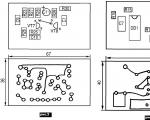
 Design. The task of creating a miniature device was not set; it was necessary to place the device and the D-0.26D battery in a plastic case with dimensions of 230x80x35 mm. The device is structurally made on four separate printed circuit boards. The amplifier board and the location of the parts on it are shown in Fig. 2, the generator board and the location of the parts on it are shown in Fig. 3, the voltage stabilizer board and the location of the parts on it are shown in Fig. 4, the detector board and the location of the parts on it are shown in Fig. .5.
This design of the device was caused by the replacement of individual blocks with new ones as a result of experiments and upgrades of the device. The modular block design always leaves a chance for “retreat”. In the option under consideration, it is much easier to carry out modernization or repairs. After all, it is easier to replace one small block than to re-create a new design on one large printed circuit board. Before placement in the specified case, the sizes of all boards were reduced (the boards were carefully cut with metal scissors).
In order to ensure the ability to measure minimum resistance values, it is necessary to minimize the resistance connecting the device input to Cx. To do this, it is not enough to use short wires. The device is installed so that the common wires of the generator, amplifier and connection points Cx are at a minimum distance from each other.
Ill-thought-out installation will easily disrupt the normal operation of the device in the 1 Ohm range, turning it into a very inconvenient and mediocre meter for this range. It is for the sake of this range that the author took on the development of this device, since the “traditional” ESR measurement range can be implemented using simpler schemes. The range of 0...1 Ohm allows you to very quickly “deal” with capacitors such as 10,000 µF or more.

Setup. Despite the presence in the circuit of six trimming resistors and other elements that require selection, setting up the device is not a complicated process. Initially, the sliders of all trimming resistors are set to the position corresponding to the maximum resistance. During setup, multi-turn resistors of the SP5-3 type were used, although the printed circuit boards were developed for the SP-38V version. After setting up the device, they were all replaced with fixed resistors.
The setup begins with CH. A resistor MLT-0.25 with a resistance of 1.2 kOhm is connected to the CH output. By selecting resistor R13, the minimum possible current through transistor VT6 is achieved, at which the CH maintains stable operation at an input voltage of 7 and up to 15 V. You should not get carried away with excessively reducing this current. Its recommended value is 100...500 µA. After setting this current, proceed to selecting resistor R14. The output voltage of the CH depends on it, the value of which was set within 6...6.3 V. The voltage drop across the CH can be further reduced by replacing resistor R12 with a wire jumper (after setting up the entire device). However, the MV is then deprived of current limitation in case of abnormal situations in the MV load.
Setting up the amplifier on transistors VT7, VT8 consists of selecting the resistance of resistor R24 to achieve a voltage gain of approximately 20 times (at the operating frequency). The accuracy of the indicated value is not important here. Much more important is the stability of the gain, which most depends on the stability of elements C10, R24, R25, VT7. Shown in the diagram in Fig. 1st contact position of switch SA1 corresponds to the 10 Ohm range. The contacts of the push-button switch SA4 are closed. Thus, instead of a capacitor Cx, a highly stable calibration resistor R21 with a resistance of 10 Ohms is connected to the input of the device. Then resistor R18 sets the voltage to 10 mV on resistor R21 (and 200 mV, if necessary, by selecting R24 on the emitter of VT8). By decreasing the resistance of resistor R5, set the arrow of the PA1 meter to the end mark of its scale (100 μA). Trimmer resistor R11 sets the digital voltmeter reading to 100 mV. If necessary, reduce the resistance of resistor R7. The presence of calibration resistors allows you to quickly assess the performance of the adjusted device.
It is also necessary to decide on the setup of the PA1 protection unit. This scheme has its own subtleties. In order not to install any additional elements - indicators for turning on the device (which certainly consume electricity, waste time and complicate the circuit), the author used the “hysteresis” of the protection circuit in terms of indicating that the device was turned on. Using resistor R8, the protection operation current is set to 130... 150 μA.
After the protection is triggered (both transistors are open), the PA1 arrow returns to a certain middle position of the scale. By changing the resistance R8, it is possible to achieve such an on state of the transistor VT2 that the pointer of the PA1 device can be “pulled” to almost any working section of the PA1 scale. This state of the protective node circuit turns out to be very stable and does not require any subsequent adjustment. The circuit owes much of this to the use of these types of transistors.
The position of the arrow in the working sector does not interfere with measurements, since the protection is not tied to the value of the operating current PA1. Short-circuiting the terminals Cx of the device or connecting a working capacitor Cx immediately causes the arrow to set to the position corresponding to the value of the measured resistance. And only an increased value of the current through PA1 again activates the protection. Many measuring instruments can be equipped with such excellent protection. The protection is configured once and the resistance of resistor R8 is not changed anymore. Otherwise, additional adjustment of the device will be required due to a change in the total resistance of resistors R7 and R8.
Next, switch switch SA1 to the position corresponding to the 1 Ohm range. In the same way as when setting the device in the 10 Ohm range, but more carefully, short-circuit the SA4 pins. Despite the fact that precision calibration resistors were used in the design, they had to be selected. The reason for this turned out to be the presence of significant resistance introduced by the wires and contacts SA4, SA 1.2. Therefore, in the 1 Ohm range, when setting, the contacts of both switches are closed (with the button, setting is inconvenient, so its contacts were short-circuited even when setting in the 10 Ohm range). The fact is that the device easily records the transition resistances of the contacts of switches SA1.2 and SA4.
In this circuit, contacts SA1 and SA4 carry virtually no current load. For this purpose, the push-button version SA4 was used, which virtually eliminates the supply of energy from an undischarged capacitor Cx to these switches. This means that their contact resistances will be stable in the long term. As a result, they can be stably “neutralized” by reducing the resistances R20, R21. In the original version of the device, a 22 Ohm resistor (MLT-0.5) is connected in parallel with R20 and a 130 Ohm resistor (MLT-0.5) is connected in parallel with R21.
Adjustment operations are repeated to ensure maximum measurement accuracy on both ranges. Of course, the device should not indicate completely different readings on different ranges with the same capacitor Cx connected. In the 1 Ohm range, the setting requires setting the voltage on the digital voltmeter display to 100 mV using trimming resistor R6. Since this resistor is connected in parallel with resistor R5, we should not forget that the adjustment of the 1 Ohm range depends on the adjustment of 10 Ohms. This switching option is simpler in circuit design and in practice (instead of three wires, only two are suitable for the board). Lastly, the value of resistor R9 is selected so that 100 mV on the digital multimeter corresponds to 10 V of battery voltage.
Modernization of the device. If the device is needed only for stationary operating conditions, then the MV is removed from the circuit. By excluding the PA1 dial meter, the circuit is also simplified; elements R8, VT1, VT2 are removed. Instead of resistor R8, install a wire jumper. This option (without the PA1 meter) allows you to slightly reduce the power consumption of the device due to the detector circuit. After removing the pointer head, taking into account the high input resistance of the digital tester, the values of resistors R7, R10, R11 are increased by 10 times. This unloads the output of the IC, which has a beneficial effect on the operation of the IC. Capacitor C4 is replaced with non-electrolytic K10-17-2.2 μF. However, in order to increase the reliability of the device, all electrolytic capacitors were subsequently replaced by non-electrolytic ones (K10-17-2.2 μF).
If this device is used together with a digital multimeter having a range of 0...200 mV or 0...2000 mV, it is easy to expand the range of measured resistances “up”, i.e. up to 20 Ohm. You just need to re-select the values of elements R7 and R10.
Clarification. In the specification of the parts used in the device, which is given in the first part of the article (RA 3/2005, p. 24, 3rd column, 3rd paragraph from the top), the resistance of resistors R19, R22 should not be 330 kOhm, but 330 Ohm. We apologize.
Literature
1. Novachenko I.V. Microcircuits for household radio equipment. - M.: Radio and communication, 1989.
2. Zyzyuk A.G. Features of repair of amplifiers WS-701//Radioa-mator.-2004.-No.6.-P.11-13.
3. Zyzyuk A.G. Some features of SDU repair//Radyamator. -2004.-No. 7. pp. 12-13.
4. Zyzyuk A.G. Mini-drill for a repairman and radio amateur//Radyuama-tor.-2004.-No. 8.-P.20-21.
5. Zyzyuk A.G. Simple capacitance meter // Radiator. - 2004. -№9. - P.26-28.
6. Zyzyuk A.G. About simple and powerful voltage stabilizers//Electric.-2004.-No.6.-P.10-12.
7. Zyzyuk A. G. Stable current generator for charging batteries and its application in the repair and design of radio-electronic equipment // Electrician. - 2004. - No. 9. - P.8-10.
8. Radiator. Best of 10 years (1993-2002). - K.: Radyuamator, 2003. How to make an LED lamp powered by 220 V
I not only learned from others that such a meter is necessary for a radio amateur, but also felt it myself when I undertook to repair an old amplifier - here you need to reliably check each electrolyte on the board and find the one that has become unusable or replace them 100%. Selected check. And I almost bought an advertised device called “ESR - mikro” via the Internet. What stopped me was the fact that they praised him too much - “over the edge.” In general, I decided to take independent action. Since I didn’t want to take any chances, I chose the simplest, if not primitive, scheme, but with a very good (thorough) description. I delved into the information and, having some inclination towards drawing, began to design my own version of the printed circuit board. To fit into the case of a thick felt-tip pen. It didn’t work out - not all the details were included in the planned scope. I thought better of it, drew a signet in the image and likeness of the author’s, etched it and assembled it. I managed to assemble it. Everything turned out very thoughtfully and neatly.
But the probe didn’t want to work, no matter how much I fought with it. But I didn’t want to retreat. For a better understanding of the diagram, I redrew it in my own way. And so “dear” (in two weeks of ordeal), it became more understandable visually.
ESR meter circuit

And I finished the printed circuit board in a cunning way. It became “double-sided” - on the second side I placed parts that did not fit on the first. To simplify the solution to the difficulty that arose, I placed them in a “canopy”. There's no time for elegance here - you need a sampler.

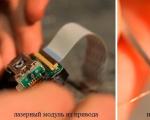
I etched the printed circuit board and soldered the parts. This time I placed the microcircuit on the socket, adapted a connector to supply power, which can be securely fixed to the board using soldering and the case can then be “hung” on it. But the trimmer resistor, with which the probe worked best, I found only this one - far from miniature.

The reverse side is the fruit of pragmatism and the pinnacle of asceticism. Something can only be said here about the probes, despite the elementary design, they are quite convenient, and the functionality is generally beyond all praise - they are capable of contact with an electrolytic capacitor of any size.

I placed everything in a makeshift case, the mounting location was the threaded connection of the power connector. Accordingly, the power minus went to the case. That is, it is grounded. Whatever it is, it is protected from interference and interference. The trimmer is not included, but it is always “at hand” and will now be a potentiometer. The plug from the radio broadcast speaker will, once and for all, avoid confusion with the multimeter sockets. Powered by a laboratory power supply, but using a personal cable with a plug from a Christmas tree garland.

And it, this unprepossessing miracle, took over and started working, right away and as it should. And there are no problems with adjustment - corresponding to one ohm, one millivolt is easily set, approximately in the middle position of the regulator.

And 10 Ohms corresponds to 49 mV.

A working capacitor corresponds to approximately 0.1 Ohm.

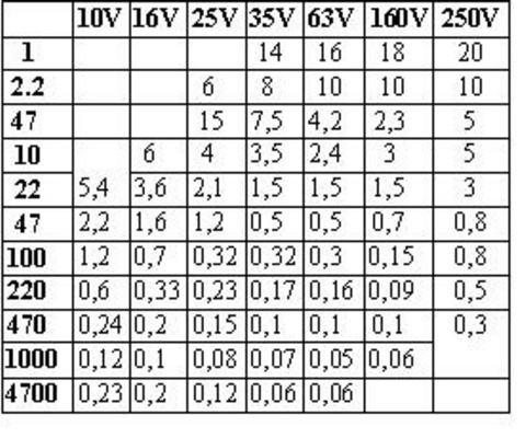
Faulty capacitor, corresponds to more than 10 ohms. The probe coped with the task; faulty electrolytic capacitors were found on the board of the device being repaired. All details regarding this scheme can be found in the archive. The maximum permissible ESR values for new electrolytic capacitors are shown in the table:
And some time later I wanted to give the console a more presentable look, but the learned postulate “the best is the enemy of the good” did not allow me to touch it - I’ll make another one, more elegant and perfect. Additional information, including a diagram of the original device, is available in the appendix. He told about his troubles and joys Babay.
Discuss the article ATTACHMENT TO THE MULTIMETER ESR METER
In the eighth issue of Radio magazine for 2011, the article “ ESR meter - attachment to a multimeter y" and many readers have encountered difficulty in purchasing the 74AC132 microcircuit or its analogues.
Indeed, this microcircuit, consisting of four two-input Schmitt triggers, turned out to be not only relatively scarce, but also more expensive compared to others that have six single-input inverting Schmitt triggers, for example 74AC14N. was modified for this microcircuit and its analogues from various manufacturers.
Modified ESR meter circuit shown in Fig. 1, and a drawing of a printed circuit board with the arrangement of elements is shown in Fig. 2. Only the meter components associated with the use of a microcircuit containing inverting Schmitt triggers underwent changes. Thus, the polarity of the diode VD1 has been changed to invert generator pulses of duration t r. At the outputs of triggers DD1.2-DD1.4, which perform the function of a buffer, the pulses take the same form. In circuit R3C2, to generate measurement pulses with a duration of tmeas at the output of trigger DD1.6, due to the lack of a second input, an additional diode VD2 is connected in parallel with resistor R3. The bottom terminal of capacitor C2 in the diagram is connected to the positive power line to simplify the layout of the printed circuit board.

Triggers DD1.2-DD1.4, loaded by resistor R4 (270 Ohm) in the “x0.1” position of switch SA1, are connected in parallel, which allows the use of the DD1 microcircuit from the 74NS series with a lower load capacity than that of the 74AC series. Therefore, instead of the one indicated in the diagram, you can use not only 74AC14RS, SN74AC14N, MC74AC14N, but also 74HC14N, MM74HC14N, SN74HC14N, as well as the domestic KR1554TL2.

Resistors R6 and R7 are now connected in parallel, which, in the fair opinion of readers, makes setup easier, since this does not require resistors with a resistance of several ohms, which are not always available at hand. When desoldering, the IRLML6346 (VT1) surface-mount transistor should be installed with the top side of the case (on which its type is indicated) to the board.
Anyone who regularly repairs electronic equipment knows what percentage of malfunctions are caused by defective electrolytic capacitors. Moreover, if a significant loss of capacity can be diagnosed using a conventional multimeter, then such a very characteristic defect as an increase in equivalent series resistance (ESR) is fundamentally impossible to detect without special devices.
For a long time, when carrying out repair work, I managed to do without specialized instruments for checking capacitors by substituting known good ones in parallel with the “suspected” capacitors; in audio equipment, use checking the signal path by ear using headphones, and also use indirect defect detection methods based on personal experience , accumulated statistics and professional intuition. When we had to join the mass repair of computer equipment, in which electrolytic capacitors account for a good half of all faults, the need to control their ESR became, without exaggeration, a strategic task. Another significant circumstance was the fact that during the repair process, faulty capacitors very often have to be replaced not with new ones, but with dismantled ones from other devices, and their serviceability is not at all guaranteed. Therefore, the moment inevitably came when I had to seriously think about solving this problem by finally acquiring an ESR meter. Since purchasing such a device was obviously out of the question for a number of reasons, the only obvious solution was to assemble it yourself.
An analysis of circuit solutions for constructing EPS meters available on the Internet has shown that the range of such devices is extremely wide. They differ in functionality, supply voltage, used element base, frequency of generated signals, presence/absence of winding elements, form of displaying measurement results, etc.
The main criteria for choosing a circuit were its simplicity, low supply voltage and a minimum number of winding units.
Taking into account the totality of factors, it was decided to repeat Yu. Kurakin’s scheme, published in an article from the magazine “Radio” (2008, No. 7, pp. 26-27). It is distinguished by a number of positive features: extreme simplicity, the absence of high-frequency transformers, low current consumption, the ability to be powered by a single galvanic cell, and low frequency of generator operation.
Details and design. The device, assembled on a prototype, worked immediately and after several days of practical experiments with the circuit, a decision was made on its final design: the device should be extremely compact and be something like a tester, allowing the measurement results to be displayed as clearly as possible.
For this purpose, a dial indicator of the M68501 type from the Sirius-324 Pano radio with a total deviation current of 250 μA and an original scale calibrated in decibels, which was at hand, was used as a measuring head. Later, I discovered similar solutions on the Internet using tape level indicators made by other authors, which confirmed the correctness of the decision made. As the body of the device, we used the case from a faulty LG DSA-0421S-12 laptop charger, which is ideal in size and has, unlike many of its counterparts, an easily disassembled case held together with screws.

The device uses exclusively publicly available and widespread radio elements available in the household of any radio amateur. The final circuit is completely identical to the author's, with the only exception being the values of some resistors. The resistance of resistor R2 should ideally be 470 kOhm (in the author’s version - 1 MOhm, although approximately half of the engine stroke is still not used), but I did not find a resistor of this value that has the required dimensions. However, this fact made it possible to modify resistor R2 in such a way that it simultaneously acts as a power switch when its axis is rotated to one of the extreme positions. To do this, it is enough to scrape off with the tip of a knife part of the resistive layer at one of the outer contacts of the resistor “horseshoe”, along which its middle contact slides, over a section of approximately 3...4 mm in length.

The value of resistor R5 is selected based on the total deflection current of the indicator used in such a way that even with a deep discharge of the battery, the ESR meter remains operational.
The type of diodes and transistors used in the circuit is absolutely uncritical, so preference was given to elements with minimal dimensions. The type of capacitors used is much more important - they should be as thermally stable as possible. As C1...C3, imported capacitors were used, which were found in the board from a faulty computer UPS, which have a very small TKE and have much smaller dimensions in comparison with domestic K73-17.
The inductor L1 is made on a ferrite ring with a magnetic permeability of 2000 Nm, having dimensions of 10 × 6 × 4.6 mm. For a generation frequency of 16 kHz, 42 turns of PEV-2 wire with a diameter of 0.5 mm are required (the length of the winding conductor is 70 cm) with an inductance of 2.3 mH. Of course, you can use any other inductor with an inductance of 2...3.5 mH, which will correspond to the frequency range of 16...12 kHz recommended by the author of the design. When making the inductor, I had the opportunity to use an oscilloscope and an inductance meter, so I selected the required number of turns experimentally solely for reasons of bringing the generator exactly to a frequency of 16 kHz, although, of course, there was no practical need for this.
The probes of the EPS meter are made non-removable - the absence of detachable connections not only simplifies the design, but also makes it more reliable, eliminating the potential for broken contacts in the low-impedance measuring circuit.

The printed circuit board of the device has dimensions of 27x28 mm, its drawing in .LAY6 format can be downloaded from the link https://yadi.sk/d/CceJc_CG3FC6wg. The grid pitch is 1.27 mm.
The layout of the elements inside the finished device is shown in the photo.

Test results. A distinctive feature of the indicator used in the device was that the ESR measurement range was from 0 to 5 Ohms. When testing capacitors of significant capacity (100 μF or more), most typical for filters in power supply circuits of motherboards, power supplies for computers and TVs, laptop chargers, network equipment converters (switches, routers, access points) and their remote adapters, this range is extremely convenient , since the scale of the device is maximally stretched. Based on the averaged experimental data for the ESR of electrolytic capacitors of various capacities shown in the table, the display of measurement results turns out to be very clear: the capacitor can be considered serviceable only if the indicator needle during measurement is located in the red sector of the scale, corresponding to positive decibel values. If the arrow is located to the left (in the black sector), the capacitor from the above capacitance range is faulty.

Of course, the device can also test small capacitors (from about 2.2 μF), and the device readings will be within the black sector of the scale, corresponding to negative decibel values. I got approximately the following correspondence between the ESR of known-good capacitors from a standard series of capacitors and the instrument scale calibration in decibels:

First of all, this design should be recommended to novice radio amateurs who do not yet have sufficient experience in designing radio equipment, but are mastering the basics of repairing electronic equipment. The low price and high repeatability of this EPS meter distinguish it from more expensive industrial devices for similar purposes.
The main advantages of the ESR meter can be considered the following:
— extreme simplicity of the circuit and availability of the element base for its practical implementation while maintaining sufficient functionality of the device and its compactness, no need for a highly sensitive recording device;
— no need for adjustments that require special measuring instruments (oscilloscope, frequency meter);
- low supply voltage and, accordingly, low cost of its source (no expensive and low-capacity “Krona” is required). The device remains operational when the source is discharged even to 50% of its rated voltage, that is, it is possible to use elements to power it that are no longer capable of functioning normally in other devices (remote controls, watches, cameras, calculators, etc.);
- low current consumption - about 380 µA at the time of measurement (depending on the measuring head used) and 125 µA in standby mode, which significantly extends the life of the power source;
- minimum quantity and extreme simplicity of winding products - any suitable choke can be used as L1 or you can easily make it yourself from scrap materials;
— a relatively low frequency of generator operation and the ability to manually set zero, allowing the use of probes with wires of almost any reasonable length and arbitrary cross-section. This advantage is undeniable in comparison with universal digital element testers that use a ZIF panel with deep contacts to connect the capacitors being tested;
— visual clarity of the display of test results, allowing you to quickly assess the suitability of the capacitor for further use without the need for an accurate numerical assessment of the ESR value and its correlation with a table of values;
— ease of use — the ability to perform continuous measurements (unlike digital ESR testers, which require pressing the measurement button and pausing after connecting each capacitor being tested), which significantly speeds up the work;
— it is not necessary to pre-discharge the capacitor before measuring ESR.
The disadvantages of the device include:
- limited functionality in comparison with digital ESR testers (lack of ability to measure capacitance of the capacitor and the percentage of its leakage);
— lack of exact numerical values of measurement results in ohms;
- relatively narrow range of measured resistances.
In recent years, specialists and radio amateurs have found it useful to estimate the equivalent series resistance (ESR) of oxide capacitors, especially in the repair practice of pulsed power supplies, high-quality UMZCHs and other modern equipment. This article proposes a meter that has a number of advantages.
In recent years, specialists and radio amateurs have found it useful to estimate the equivalent series resistance (ESR) of oxide capacitors, especially in the repair practice of pulsed power supplies, high-quality UMZCHs and other modern equipment. This article proposes a meter that has a number of advantages.
A scale that is convenient for a device with a dial indicator, close to logarithmic, allows you to determine ESR values in approximately the range from fractions of an ohm to 50 ohms, with the value of 1 ohm appearing in the section of the scale corresponding to 35...50% of the total deviation current. This makes it possible to estimate with acceptable accuracy ESR values in the range of 0.1...1 Ohm, which, for example, is necessary for oxide capacitors with a capacity of more than 1000 μF, and with less accuracy - up to 50 Ohm.
Complete galvanic isolation of the measurement circuit maximally protects the device from failure when testing an accidentally charged capacitor - a situation that is not uncommon in practice. Low voltage on the test leads (less than 70 mV) allows measurements in most cases without soldering capacitors. Powering the device from one galvanic cell with a voltage of 1.5 V is accepted as the most optimal option (low cost and small dimensions). There is no need to calibrate the device and monitor the voltage of the element, since there is a built-in stabilizer and an automatic switch when the supply voltage is less than the permissible limit with a switch-on lock. And finally, quasi-touch switching on and off of the device using two miniature buttons.
Main technical characteristics
Interval of measured resistance, Ohm.........0.1...50
Frequency of measuring pulses, kHz...................120
Pulse amplitude on the meter probes, mV........50...70
Supply voltage, V
nominal...................1.5
permissible...............0.9...3
Current consumption, mA, no more...........................20
The electrical circuit diagram of the device is shown in Fig. 1

A voltage converter that increases from 1.5 to 9 V is assembled using transistors VT1, VT2 and transformer T1. Capacitor C1 is a filter capacitor.
The output voltage of the converter is supplied through an electronic switch on the SCR VS1, which, in addition to manually turning the device on and off, automatically turns it off when the supply voltage is low, is supplied to a micropower stabilizer assembled on the DA1 chip and resistors R3, R4. A stabilized voltage of 4 V powers a pulse generator assembled according to a standard circuit using six NAND elements of the DD1 microcircuit. Circuit R6C2 sets the frequency of the test pulses to approximately 100...120 kHz. LED HL1 is an indicator that the device is turned on.
Through the separating capacitor SZ, pulses are supplied to transformer T2. The voltage from its secondary winding is applied to the capacitor being tested and to the primary winding of the measuring current transformer TZ. From the secondary winding of the TZ, the signal is supplied through a half-wave rectifier using diode VD3 and capacitor C4 to the pointer microammeter RA1. The larger the ESR of the capacitor, the smaller the deviation of the meter needle.
The thyristor switch operates as follows. In the initial state, there is a low voltage at the gate of the field-effect transistor VT3, since the thyristor VS1 is closed, as a result of which the power supply circuit of the device is disconnected along the negative wire. In this case, the load resistance of the boost converter is almost infinite and it does not work in this mode. In this state, the current consumption from battery G1 is practically zero.
When the contacts of the SB2 button are closed, the voltage converter receives a load formed by the resistance of the control electrode-cathode transition of the SCR and resistor R1. The converter starts and its voltage opens the thyristor VS1. Field-effect transistor VT3 opens, and the negative power circuit of the stabilizer and generator is connected to the converter through a very low resistance of the channel of field-effect transistor VT3. The SB1 shutdown button, when pressed, bypasses the anode and cathode of the thyristor VS1, as a result, the transistor VT3 also closes, turning off the device. Automatic shutdown when the battery voltage drops occurs when the current through the thyristor becomes less than the holding current in the open state. The voltage at the output of the boost converter at which this occurs is selected so that it is sufficient for normal operation of the stabilizer, i.e., so that the minimum permissible difference in voltage values at the input and output of the DA1 microcircuit is always maintained.
Construction and details
All parts of the device, with the exception of a microammeter and two buttons, are located on a single-sided printed circuit board measuring 55x80 mm. The board drawing is shown in Fig. 2. The body of the device is made of foil getinax. Under the microammeter there are miniature buttons from the TV.

All transformers are wound on 2000NM ferrite rings of standard size K10x6x4.5, but these dimensions are not critical. Transformer T2 has two windings: primary - 100 turns, secondary - one turn. In the TZ transformer, the primary winding consists of four turns, and the secondary winding consists of 200 turns. The diameter of the wires of the windings of transformers T2 and TZ is not critical, but it is advisable to wind those that are included in the measuring circuit with a thicker wire - approximately 0.8 mm, the other windings of these transformers are wound with PEV-2 wire with a diameter of 0.09 mm.
Transistors VT1 and VT2 - any from the KT209 series. It is advisable to select them with the same base current transfer coefficient. You can use any capacitors that are suitable in size: resistors - MLT with a power of 0.125 or 0.25 W. Diodes VD1 and VD2 - any medium power. Diode VD3 - D311 or any of the D9 series. The VT3 field-effect transistor is almost any n-channel one with a low open channel resistance and a low gate-source threshold voltage; for compact installation, part of the base has been removed from the IRF740A transistor.
The LED is suitable for any high brightness, the glow of which is already visible at a current of 1 mA.
Microammeter RA1 - M4761 from an old reel-to-reel tape recorder, with a total needle deflection current of 500 μA. A piece of shielded wire 20 cm long is used as a probe. A suitable ballpoint pen body is put on it, and thin steel needles are soldered to the end of the central core and to the screen braid of the wire. The needles are temporarily fixed at a distance of 5 mm from each other, the probe body is slightly pushed onto them and the joint is filled with hot glue; the joint is formed into a ball with a diameter of slightly less than a centimeter. Such a probe, in my opinion, is the most optimal for such meters. It is easy to connect to a capacitor by placing one needle on one terminal of the capacitor and the other touching the second terminal, similar to working with a compass.
About setting up the device.
First of all, check the operation of the boost converter. As a load, you can temporarily connect a 1 kOhm resistor to the output of the converter. Then temporarily connect the anode and cathode of the SCR with a jumper and set the voltage at the output of the DA1 stabilizer to approximately 4 V with resistor R3. The generator frequency should be within 100... 120 kHz.
Next, they close the probe needles with a conductor and adjust the tuning resistor R3 to set the microammeter needle just below the maximum position, then, trying to change the phasing of one of the measurement windings, achieve the maximum readings of the device and leave the windings in this connection. By adjusting resistor R3, set the arrow to maximum. By connecting a non-wire resistor with a resistance of 1 ohm to the probes, check the position of the arrow (it should be approximately in the middle of the scale) and, if necessary, changing the number of turns in the primary winding of the TZ transformer, change the stretching of the scale. At the same time, each time setting the microammeter needle to the maximum using adjustment R3.
The most optimal scale seems to be one on which ESR readings of no more than 1 ohm occupy approximately 0.3...0.5 of its entire length, i.e., readings from 0.1 to 1 ohm are freely distinguishable every 0.1 ohm. The device can use any other microammeters with a total deviation current of no more than 500 μA: for more sensitive ones, it will be necessary to reduce the number of turns of the secondary winding of the TZ transformer.
Next, they set up the shutdown unit by selecting resistor R1; instead of it, you can temporarily solder a trimmer resistor with a resistance of 6.8 kOhm. After supplying power to the DA1 input from an external regulated source, use a voltmeter to monitor the voltage at the DA1 output. You should find the lowest input voltage of the stabilizer at which the output does not yet begin to fall - this is the minimum operating input voltage. It must be borne in mind that the lower the minimum operating voltage, the more fully the battery resource will be used.
Next, by selecting resistor R1, the thyristor closes abruptly at a supply voltage slightly higher than the minimum permissible. This is clearly visible from the deflection of the instrument needle. When the probes are closed, it should drop sharply from maximum to zero, and the LED goes out. The thyristor must close earlier than the field-effect transistor VT3; otherwise there will be no sudden shifting. Next, manually switching on and off is checked again using the SB1 and SB2 buttons.
Finally, the meter scale is calibrated using non-wire resistors of appropriate ratings. The use of the device in repair practice has shown its greater efficiency and convenience compared to other similar devices. They can also successfully test the contact resistance of various buttons, reed switches and relays.
Article taken from the website www.radio-lubitel.ru