Creating cd rom. Creating a CD-ROM area on a USB flash drive. cause eye damage or cause skin burns, this is no fun
Before you throw away your old drive that runs an electric motor or laser, you might want to think about how you can still use it. In fact, there is a use for it, although not as a player or reading device.
To regulate the rotation speed, power is supplied to the electric motor through a rheostat to slow down the rotation speed. A neat round stand is installed on the rotating part, and the device is ready.
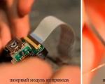
A Chinese pointer can serve as a housing for the device, and a laser diode is removed from a DVD or CD-RW drive (a weaker version is a CD-R drive). Visually, it resembles a schematic image of a hat. You will need the top and middle contacts of the diode, as plus and minus, respectively. Power is supplied from two AA batteries. Attention! It is strictly forbidden to shine a pointer into the eyes of people and animals!

The idea is simple, like everything ingenious - all the contents are removed from the case of a faulty CD drive, without removing the front panel, and make sure that the buttons do not fall out of it. The cache turns out to be quite impressive, and a metal detector will not reveal it.

Sharpening machine
A device with a working electric motor can easily serve as a small sharpening machine for sharpening drills or small knives. To do this, you need to remove the top cover of the drive, stick the abrasive onto the CD and slightly improve it, as shown in the video:
To create a fan, you will need a 6-volt electric motor, an impeller, a motor holder, and a DC source, such as a power supply or AA batteries.

More ideas...
How else to use your outdated device? The driving mechanism of the laser is used to make engravers, cutters, and plotters. Use the lens in a homemade microscope. The use of the housing, laser and engine was discussed above. If the device is still working, you can connect speakers and a power supply to it, you will get a player. As a last resort, you can donate it or sell it for spare parts.
CD-ROM on a flash drive is a very convenient thing. This is 100% compatible with ISO images and guaranteed to work from the computer's BIOS. This will allow you to boot from a flash drive like a regular CD-ROM. That is, the computer will never know that it is being “deceived.”
The era of optical drives is ending. In modern computers, a CD-ROM drive (DVD, DVD-ROM, DVD-RW, CD-RW) is becoming a rarity. Therefore, users have to “get out” in every possible way when they need to install the operating system. In order not to look for an external USB optical drive, it has long been possible to boot from a flash drive. And all modern computers have such support in the BIOS. But no, no, yes, a situation arises like in Viktor Tsoi’s song “everything is in place, but something is wrong.” Many times I came across a situation where the computer booted from only one flash drive out of five. And the only way out of this situation is to create (emulate) a CD-ROM on a USB flash drive. That is, when the computer sees the USB flash drive as a real optical drive.
There are many solutions on the Internet regarding this matter. They all present a bit of a puzzle. In which you first need to find out the type of controller on the flash drive, the organization and model (brand) of memory. Then, for this hardware, you need to find a special program for reprogramming the controller and uploading an ISO image. At the same time, not all controllers used in flash drives have the ability to emulate CD-ROMs. That is, it’s not a fact that your flash drive can do this at all. And the saddest thing is that even if you follow all the instructions exactly, there is a high chance of ruining the flash drive.
The ideal option in such a situation is to purchase a flash drive for which the manufacturer itself has provided the possibility of creating a CD-ROM. One day I came across a Transcend JetFlash 620 8Gb flash drive.
A distinctive feature of which is the presence of a built-in virtual CD-ROM. This means that the controller supports the creation of CD-ROMs and we are halfway to success.
How to create a CD-ROM on a Transcend JetFlash 620 8Gb flash drive
To create a CD-ROM on a Transcend JetFlash 620 8Gb flash drive, you need to download the diagnostic and recovery utility for this USB drive model JetFlash Online Recovery from the official website. At the time of writing, the current version of the program for Windows is v9.0.0.8 (JetFlash 620) for the Transcend JetFlash 620 8Gb flash drive. The program size is 5.7 MB.
After downloading the archive, you will need to unpack the EXE file contained in it. For me it is OnLineRecovery_JF620_v9.0.0.8.exe. This is a self-extracting archive, inside of which there is the OnLineRecovery_620.exe utility and the CD-ROM image file security_f.iso.
So, here is the main secret of this article. In order to create a virtual CD-ROM on a Transcend JetFlash 620 flash drive, you need to rename the ISO image file you need, for example, the operating system installation distribution, to security_f.iso and place it next to the OnLineRecovery_620.exe recovery utility. After that, run the utility and it will create two partitions on the flash drive, one of which will record your ISO image, which will be recognized by computers as a USB-CD-ROM, and the remaining space will be a regular flash drive. It's that simple.
I hope there is no need to warn you that as a result of the JetFlash Online Recovery recovery utility, all data from the flash drive will disappear.
Users who lived through the early 2000s probably remember the times when films, computer games, programs and music were delivered to our computers only using CD/DVD discs, which were common at that time. No one knew about free downloading of data on the Internet, torrents and YouTube. The situation was saved by optical drives, with the help of which information was transferred to the computer’s hard drive.
The rapid development of Internet technologies has called into question the need to have such a component as a “disk drive”. In today's desktop systems and laptops you rarely see a drive. All because of virtual disks, which replaced “blanks” and became commonplace. However, not everyone was able to make a comfortable transition to the new technology. In this article we will try to correct this situation and explain in detail the essence of the creation process, the nuances of use and other questions that have repeatedly arisen for everyone who does not know how to use a virtual CD ROM.
When you might need it
Many may doubt the idea of using an innovation that has caught on with some people and simply continue to use the optical drive, using it to rewrite images and information onto physical media. However, the archaic version loses in some cases, the most common of which are:
- Missing or faulty disk drive. Any part does not have an eternal service life. Sooner or later, a problem may arise, and it’s good if it does not happen at the most necessary moment (which, according to the “law of meanness,” happens often). In addition, the “system specialist” receiving the disk with information from you may simply not have an optical drive. But a virtual CD-ROM is available on any modern PC (if you devote some time to creating it).
- Multichannel. I have rarely come across computers that had multiple disk drives at once. Users who often work with recording and reading discs had to constantly rearrange CD/DVDs. There are no such problems with virtual disks, which means you can work with several at once.
- Convenient data transfer. To exchange information recorded on a disc, you need to personally hand over the media to the receiving party. In the case of virtually recorded images, the transfer is carried out online, over the Internet.
Creating a virtual CD-ROM
To read virtual images (iso files; mdf, bwi, mds and others), you need to create a virtual CD-ROM, which, like an optical drive, reproduces (emulates) data from the drive. You can create a virtual disk using special software, such as Daemon Tools, Virtual Drive. Their operating principle is identical, and the functionality is largely similar. For example, we took the last one listed, since its capabilities and tools are very easy to cope with even for a user who is far from such processes.
- First, download the Alcohol 120% program installer using a link from the Yandex disk, or on the developer’s official website. Install it on your computer.
- Let's launch the program. First of all, we need to create a virtual CD drive. To do this, in the “Settings” section, select the option "Virtual disk".
- In the menu that opens, manually select the number of virtual disks to be created. Confirm the result by clicking on the OK button.
The drive has been successfully created, which we can see in the “Device” panel or in the “My Computer” folder.
- Now let's open the finished image. To do this, select the “File” tab, and in the menu that opens, click on “Open…” (or simply use the key combination Ctrl + O).
- We find the image file we need, select it with LMB and click on the “Open” button.
The image has been added to the library for processing.
- Now you need to read the previously added file. To do this, select the RMB image, and in the drop-down menu select the option "Mount to device".
The job is done. We can see the result in the “Computer” folder, where the installer located in the virtual drive will be listed among the reading devices.
After performing operations with the image, you need to remove it from the virtual drive. To do this, using the Alcohol 120% program, in the menu of available drives, select our BD-ROM with the right mouse button and select the function from the list "Dismantle image". The disk will be empty again.
If you want to remove the virtual drive altogether, you need to repeat similar steps as when creating it:
- In the available devices, click on the DVD/CD drive RMB. In the list that appears, click “Properties”.
- Set the value back to “0” in the section for selecting the number of virtual disks and click “OK”.
Adding a virtual hard disk
The above opportunities have been available to many for a decade now. The popularity of using a virtual data reader has led to the emergence of a similar phenomenon called a virtual hard disk. This technology allows you to create a file (with a VHD extension) that is displayed in Explorer as a standard partition on your hard drive. Everyone decides for themselves the rationality of using a virtual drive: some reorganize free space on volumes in this way, others even install an OS. Don’t forget about the ability to create a secure file container, thus limiting information from attacks by other users.
We will create a virtual hard disk using standard Windows tools (this function is available on Windows 7, 8.1, 10). However, with the help of special software you can achieve a similar result. Daemon Tools Ultra, as well as Disk2vhd, cope with this task most effectively. These programs have separate sections dedicated to creating virtual disks (both drives and drives like HDDs).
- Open the “Run” service by simultaneously pressing the Win + R keys. Enter the command diskmgmt.msc into the empty line and click OK.
- The service will open "Disk Management". In the control menu, activate the "Action" tab, and in it select "Create a virtual hard disk".
- In the window that appears, you need to specify the location of the file to be created, select the format (VHD/VHDX), and also determine the possibility of extending the file.
- The file has been created, but the disk has not yet been initialized. By right-clicking on the disk, select the option "Initialize disk".
- In the next window, you need to specify the partition style (we recommend GUID if you intend to limit yourself to standard capabilities for working with the allocated space).
Connecting the drive after rebooting the PC
Unfortunately, working with a virtual hard disk requires remounting the VHD/VHDX file after each session is completed. Fortunately, we don’t have to create a new disk, initialize a partition, or create a volume. To return the virtual disk to work (emulate data), you must perform the following steps:

We hope that with the help of our article you learned how to create a virtual disk, and also determined the benefits of using it.
We also watch the video
CD-partitions on a flash drive allow you to boot without problems on a PC, where loading from a regular flash drive (With Public- flash drive section) impossible. Download from CD-Areas of a flash drive usually work everywhere.
But you should understand that using a flash drive as a boot device from BIOS, is not the intended purpose of this controller function.
And the main function CDROM- the area is that a specific flash drive manufacturer can place there the necessary software for encryption, virus protection, or simply some advertising information.
Therefore, the successful outcome of loading any component as from a normal CD-drive, mainly depends on the compatibility of the specific controller with a specific motherboard, on which you boot.
WHICH CONTROLLERS ARE MOST SUITABLE
I personally, for use as LiveUSB and reinstallation Windows, I recommend only controllers SMI And Phison, because they are most compatible with older motherboards.
U SMI-chips, the highest loadability from under BIOS showed models SM3257AA and those older (For example SM3257ENAA And SM3257ENLT) .
WITH Phison, problems of a slightly different order, which are only indirectly related to loading efficiency. All controllers can be divided into two groups, in the first there are the so-called PS2XXX (For example PS2232 And PS2239) , and in the second PS2251-XX(For example PS2251-38 And PS2251-03). So, chips from the first group cannot be converted into MODE30, but only in MODE21, which contains an additional flash-section that negatively affects the level of compatibility.
If you don’t have an old computer, then other models will be suitable, but still not all. For example, controllers Alcor, have never been known for their good downloadability and in general this is not their topic.
And here are the chips Innostor who became famous for their USB3.0 models, although they are crooked to load, can simultaneously carry up to 6 ISO-disk images!
Below, utilities for manufacturers will be considered USB-controllers capable of working with CD-section. There you can also find a complete list of suitable hardware flash drives for this purpose.
SEVERAL CDROM PARTITIONS ON ONE FLASH DRIVE
Speaking specifically about simultaneously working CD-ROM areas on a flash drive, then I was able to curb only a few controller manufacturers. These are my favorites SMI controllers, some flash drives Phison and chips used in Chinese counterfeits Chipsbank.
On the USBDev portal, you can find detailed instructions for creating up to 7 simultaneously working SDROMs. At the same time, disk images can be changed in a couple of clicks, bypassing the flashing procedure, which minimizes subsequent risks to the limit!
Also included in the article are two videos that I specially recorded for you, in case the letters are too tough for you.
With chips from Phison, although everything is done much simpler, only under MODE32 Not all flash drives are suitable. Of those that I tried, a little more than half turned out to be suitable for working in this specific mode. Yes and MODE32 limited to only two simultaneously working SDROM ami.
Controllers Chipsbank, I liked least of all in this regard. And the creation process is longer and more tedious. And the likelihood of finding a flash drive of suitable size on it is extremely low. Yes, and the ability to flash two CDROM-section, there are only the latest chips, line CBM2098 And CBM2099.
SMI chips, controllers from Innostor, already mentioned above. They, of course, will never compare in functionality and flexibility with SMI-shki, but they at least have something in terms of multi-booting.
U Innostor, at least one section under CD-Rom, but you can write there up to 6 ISO images and through a special Windows program called Innostor AI-Burn, choose the necessary one at a given time.
The operation itself to change the flash drive is a little risky, so it is better not to do it with flash drives in non-standard buildings ( monoliths, flash drives the size of a coin, ...). That is, so that in case of incorrect completion of the controller firmware, it would be possible to disassemble the case and transfer the flash drive to test mode.
In principle, provided that you do everything correctly, the utility will fit your flash drive and create only a CD-ROM area on the flash drive, then the chance that the flash drive will freeze is very small. It’s not for nothing that I highlighted in bold that it is advisable not to create areas other than CD-ROM. Although some write that it is better to create in addition CDROM-partition is also a flash area into which you can upload files. But I am extremely skeptical about this.
What problems can there be when you create two or more areas on a flash drive:
It is very likely that when you try to return the flash drive to its original state or overwrite ISO-file, the flasher will end with an error and your flash drive will have to be flashed again or it will freeze. In this case, it will have to be converted to test mode and flash it from there. Those. if you have monolithic flash drive, you are taking quite a risk and I think the gamble is not worth the candle.
Not available on all computers. Windows flash section, although the likelihood of this is very, very small.
From under BIOS, with a decent probability, it will not be possible to load via a bootloader (such as GRUB4DOS), elements with flush- areas of the flash drive. Those. V Windows You have everything in good order, but here it’s a bummer, for example, on my computer there is such a battle.
It is possible that even with CDROM-the area does not load at all, which occurs on a very large percentage of old computers. This problem is especially acute for company controllers Innostor.
The flash drive takes noticeably longer to initialize by the computer.
I may be dramatizing the situation a little, but I just want to give you some thoughts in case you run into problems.
HOW TO FLASH TO CDROM
To create CD-areas on USB-flash drive, you need to select a utility for a specific controller installed in a specific flash drive. Sometimes when selecting, you need to consider the memory chip as the main parameter, but this is already off-topic for this article. Then configure the utilities to work with a specific combination (controller + memory), activate the settings associated with the CDROM area and then specify the path to the disk image itself (for the features of specific utilities, see below in the comments next to the exclamation mark [!]). After such an operation, the flash drive in BIOS will be determined (depending on the settings of the production utility and controller capabilities) either as CDROM-device, or as two devices ( CDROM + regular section).

Also, the quality of the result, oddly enough, depends on the utility used. For example, Alcor did not create utilities with older versions CDROM-area more 4GB or at Skymedi Bootability in LUN2 mode may depend on the version.
Let me clarify the situation with the kind of limitation in 4GB per size ISO-disk image - like this There is no 4GB limit and never was. It all depends on the capabilities of the available software versions for a particular hardware (controller + memory). So for some very old controllers, and also for some not very advanced ones, I'm not familiar with those at all. And the nonsense (about 4GB and others) that often circulates on the Internet is associated only with the mental retardation of those who write it. Often such people have never had more than 1-2 flash drives and at the same time try to teach others. Also a distinctive feature of these idiots are recommendations for searching for software using VID-PID, which are also complete nonsense.
Detailed manuals with pictures for the main controllers will be written and posted in separate articles. So you need to be patient, and I need to scrape together the desire and the deal is in the bag.
WHAT SPECIFIC UTILITIES CAN CREATE A CD-ROM SECTION
List of utilities that allow you to create a CDROM area and their features for the main controllers:
Alcor: AlcorMP_UFD, ALCOR Recovery Tool, FC MpTool, Transcend AlcorMP JF620 Online Recovery, Transcend AlcorMP V15 Online Recovery.
!: To create a Generic Autorun Disk using 'Transcend AlcorMP JF620 Online Recovery', just rename the required image to create a CD partition to security_f.iso, place it next to OnLineRecovery_620.exe and perform the flash drive recovery procedure by running OnLineRecovery_620.exe. After executing OnLineRecovery_620.exe, two partitions are always created: a CD partition with the contents of security_f.iso and a regular partition, defined in Windows as a removable disk in FAT32 format.
!: To create a Generic Autorun Disk using ‘Transcend AlcorMP V15 Online Recovery’, just rename the required image to create a CD partition to TMUS.iso, place it next to OnLineRecovery_TMUS.exe and perform the flash drive recovery procedure by running OnLineRecovery_TMUS.exe. After executing OnLineRecovery_TMUS.exe, two partitions are always created: a CD partition with the contents of TMUS.iso and a regular partition, defined in Windows as a removable disk in FAT32 format labeled Trend Micro.
!: On flash drives with Alcor controllers up to and including the AU6982 model, it has not yet been possible to create the ‘Autorun’ partition.
ChipsBank: Chipsbank APTool, Chipsbank CBM2093 UMPTool, Chipsbank UMPTool, Chipsbank V88 UMPTool, FlashDiskManager.
Innostor: Innostor MP Tool, AI-Burn, AI Partition.
!: AI-Burn – only overwrites the CD area created using the Innostor MP Tool or AI Partition.
!: AI Partition – only creates a CD area, onto which you can then burn a disk image using AI-Burn.
iTE Tech. Inc. : MPTool, DtMPTool, UFDUtility, CDROM Tool.
Phison: Phison ModeConverter, Phison MPALL, Phison USB MPTool.
!: Phison ModeConverter v1.0.1.5 is the easiest and safest way to create for modern controllers from Phison.
!: Mode = 30 (CDROM Only); Mode = 21 (CDROM + Public).
!: There may be some problems with the subsequent identification of the flash drive in utilities when creating ‘CDROM\Public + Fixed Disk‘.
Skymedi: Skymedi PDT, Skymedi SK6213 ISO Update Tool.
!: The ‘Autorun Counter’ parameter means the number of times the CDROM partition will appear in the system. In order for the section to work endlessly, enter the value 255 (==unlimited) into this field.
SMI: SMI MPTool, DYNA MPTool, uDiskToolBar, MySDKTest, UFDisk Utilities.
SSS: 3S USB MP Utility, 3S USB OnCardSorting.
!: In the utility windows there are no settings responsible for the CD area of the flash drive, so you need to edit the configuration file used (for example - 6691_CM_T32D2 TSOP 32Gb x 2.INI) as follows: approximately after the section
add section
where to add the line CDROM_ISO=j:\LIVECD\_2K10\MultiBoot_2k10_2.6.1_conty9.iso(where MultiBoot_2k10_2.6.1_conty9.iso is the file that you want to burn to the CD area).
Not all controllers have the ability to overwrite a CDROM area without re-creating other sections of the flash drive. For example, I know for sure only about two controller companies with which this operation can be carried out, namely:
Innostor: using the AI-Burn utility.
SMI: using the program MySDKTest. Despite the fact that this software fully supports only controllers up to the SM3255AB model inclusive. It can perform the procedure of replacing a disk image with any, even the most modern SMI chip.
You can usually return the flash drive to its original state using the same utilities, as well as some other utilities that you can find on my website.
This article was taken from a foreign website and translated by me personally. Contributed this article.
This project describes the design of a very low budget 3D printer that is primarily built from recycled electronic components.
The result is a small format printer for less than $100.
First of all, we will learn how the general CNC system works (assembly and calibration, bearings, guides), and then teach the machine to respond to G-code instructions. After that, we add a small plastic extruder and give commands to the plastic extrusion calibration, driver power settings and other operations that will give life to the printer. Following these instructions will give you a small 3D printer that is built with approximately 80% recycled components, which gives it great potential and helps reduce the cost significantly.
On the one hand, you get an introduction to mechanical engineering and digital fabrication, and on the other hand, you get a small 3D printer built from reused electronic components. This should help you become more proficient in dealing with problems associated with e-waste disposal.
Step 1: X, Y and Z.
Required components:
- 2 standard CD/DVD drives from an old computer.
- 1 floppy drive.
We can get these components for free by contacting a repair service center. We want to make sure that the motors we use from floppy drives are stepper motors and not DC motors.
Step 2: Preparing the motor

Components:
3 stepper motors from CD/DVD drives.
1 NEMA 17 stepper motor what should we buy. We use this type of motor for plastic extruder where there is a lot of force needed to handle the plastic filament.
CNC electronics: PLATFORMS or RepRap Gen 6/7. Important, we can use Sprinter/Marlin Open Firmware. In this example we're using RepRap Gen6 electronics, but you can choose based on price and availability.
PC power supply.
Cables, socket, heat shrink tubing.
The first thing we want to do is once we have said stepper motors, we can solder wires to them. In this case we have 4 cables for which we must maintain the appropriate color sequence (described in the data sheet).
Specification for stepper motors CD/DVD: Download. .
Specification for NEMA 17 Stepper Motor: Download. .
Step 3: Prepare the Power Supply

The next step is to prepare the power in order to use it for our project. First of all, we connect the two wires to each other (as indicated in the picture) so that there is direct power from the switch to the stand. After that we select one yellow (12V) and one black wire (GND) to power the controller.
Step 4: Checking the Motors and the Arduino IDE Program

Now we are going to check the engines. To do this we need to download the Arduino IDE (physical computing environment), can be found at: http://arduino.cc/en/Main/Software.
We need to download and install Arduino 23 version.
After this we must download the firmware. We chose Marlin, which is already configured and can be downloaded by Marlin: Download. .
After we have installed Arduino, we will connect our computer to Ramp/Sanguino/Gen6-7 CNC Controller via USB cable, we will select the corresponding serial port under Arduino IDE Tools/Serial Port, and we will select the controller type under Board Tools ( Ramps (Arduino Mega 2560), Sanguinololu/Gen6 (Sanguino W/ATmega644P - Sanguino must be installed inside Arduino)).
Basic explanation of the parameter, all configuration parameters are in the configuration.h file:
In the Arduino environment we will open the firmware, we already have the /Sketchbook/Marlin file downloaded and we will see the configuration options before we download the firmware to our controller.
1) #define MOTHERBOARD 3, according to the real hardware we use (Ramps 1.3 or 1.4 = 33, Gen6 = 5, ...).
2) Thermistor 7, RepRappro uses Honeywell 100k.
3) PID - this value makes our laser more stable in terms of temperature.
4) Step by one, this is a very important point in order to configure any controller (step 9)
Step 5: Printer. Computer management.

Controlling the printer via a computer.
Software: There are various, freely available programs that allow us to interact and control the printer (Pronterface, Repetier, ...) we use Repetier host, which you can download from http://www.repetier.com/. It's easy to install and combines layers. A slicer is a piece of software that generates a sequence of sections of the object we want to print, associates those sections with layers, and generates G-code for the machine. Slices can be adjusted using parameters such as layer height, print speed, infill, and others that are important for print quality.
Common slicer configurations can be found in the following links:
- Skeinforge configuration: http://fabmetheus.crsndoo.com/wiki/index.php/Skeinforge
- Slic3r configuration: http://manual.slic3r.org/
In our case we have a profile configuret Skeinforge for the printer, which can be integrated into the receiving write head software.
Step 6: Adjust Current and Intensity


Now we are ready to test the printer motors. Connect the computer and machine controller using a USB cable (the motors must be connected to the corresponding sockets). Launch Repetier hosting and activate communication between the software and the controller by selecting the appropriate serial port. If the connection is successful, you will be able to control the connected motors using the manual control on the right.
In order to avoid motors overheating during regular use, we will adjust the current so that each motor can receive an even load.
To do this, we will connect only one motor. We will repeat this operation for each axis. For this we need a multimeter attached in series between the power supply and the controller. The multimeter must be set to amplifier (current) mode - see figure.
Then we will connect the controller to the computer again, turn it on and measure the current using a multimeter. When we manually activated the motor through the Repetier interface, the current must increase by a certain number of milliamps (which is the current to activate the stepper motor). For each axis, the current is slightly different, depending on the pitch of the motor. You will have to adjust the small potentiometer to control the step interval and set the current limit for each axis according to the following control values:
The board conducts a current of about 80 mA
We will apply 200mA current to the X and Y axis steppers.
400mA for Z-axis, this is required due to the higher power required to raise the write head.
400 mA to power the extruder motor, since it is a high current consumer.
Step 7: Creating the Structure Machine

In the following link you will find the necessary templates for lasers that cut out parts. We used 5mm thick acrylic plates, but other materials such as wood can be used, depending on availability and price.
Laser settings and examples for the Auto Cad program: Download. .
The frame design makes it possible to build the machine without glue: all parts are assembled using mechanical connections and screws. Before laser cutting out the frame parts, make sure the motor is well secured in the CD/DVD drive. You will have to measure and modify the holes in the CAD template.
Step 8: Calibrate X, Y and Z Axis
Although the downloaded Marlin firmware already has a standard calibration for axis resolution, you will have to go through this step if you want to fine-tune your printer. Here you will be told about microprograms that allow you to set the laser pitch down to the millimeter; your machine actually needs these precise settings. This value depends on the pitches of your motor and the thread size of the moving rods of your axles. By doing this, we will ensure that the machine's movement actually matches the G-code distances.
This knowledge will allow you to build a CNC machine yourself, regardless of the component types and sizes.
In this case, X, Y and Z have the same threaded rods so the calibration values will be the same for them (some may be different if you use different components for different axes).
- Pulley radius.
- Steps per revolution of our stepper motor.
Micro-stepping parameters (in our case 1/16, which means that in one signal clock cycle, only 1/16 of the step is executed, giving higher precision to the system).
We set this value in the firmware ( stepsper millimeter).
For Z axis:
Using the Controller (Repetier) interface we configure the Z axis, which allows us to move a certain distance and measure the actual displacement.
As an example, we'll command it to move 10mm and measure an offset of 37.4mm.
There is an N number of steps defined in stepspermillimeter in the firmware (X = 80, Y = 80, Z = 2560, EXTR = 777.6).
N = N * 10 / 37.4
The new value should be 682.67.
We repeat this for 3 or 4 times, recompiling and rebooting the firmware for the controller, we get higher accuracy.
In this project we did not use the final settings to make the machine more precise, but they can easily be included in the firmware and it will be ready for us.
We are ready for the first test, we can use the pen to check that the distances in the drawing are correct.
We will assemble the direct drive as shown in the picture by attaching the stepper motor to the main frame.
For calibration, the flow of plastic should correspond to a piece of plastic thread and distance (for example 100 mm), put a piece of tape. Then go to Repetier Software and click extrude 100mm, real distance and repeat Step 9 (operation).
Step 10: Printing the first object


The device should now be ready for the first test. Our extruder uses 1.75mm diameter plastic filament, which is easier to extrude and more flexible than the standard 3mm diameter. We will be using PLA plastic, which is a bio-plastic and has some advantage over ABS: it melts at a lower temperature, making printing easier.
Now, in Repetier, we activate the profile slicing that is available for Skeinforge cutting. Download .
We print a small calibration cube (10x10x10mm) on the printer, it will print very quickly and we will be able to detect configuration problems and motor step loss by checking the actual size of the printed cube.
So, to start printing, open the STL model and slice it using the standard profile (or the one you downloaded) from Skeinforge cutting: we will see a representation of the sliced object and the corresponding G-code. We heat up the extruder and when it reaches the melting temperature of the plastic (190-210C depending on the plastic grade) we extrude some material (extrusion press) to see that everything is working properly.
We set the origin relative to the extrusion head (x = 0, y = 0, z = 0), use paper as a separator, the head should be as close to the paper as possible, but not touching it. This will be the starting position for the extrusion head. From there we can start printing.