Simple vertical antenna 144 430
The antenna of the UA9GL design has proven itself well and competes even with more complex antennas when conducting radio communications, both through troppo, aurora and through EME. The antenna has a gain of about 17-18 dB relative to the dipole and is considered one of the best antennas.The antenna is easy to build, practically does not require any additional costs, and everything is clearly clear from the drawings. The materials used here can be replaced with similar ones in compliance with the naturally recommended dimensions. The power cable for this antenna is a common 75 ohm one. All antenna dimensions are shown in Fig.1. At the top are the dimensions of the lengths of the antenna elements, and at the bottom are the distances between them.
Figure 2 shows the dimensions of the active vibrator; the main requirement for the vibrator is that the ratio of the upper to lower diameters should be equal to 3.
In our example, top = 6 mm and bottom = 2 mm. The ends of the wire must be inserted inside and well secured there, soldered, and crimped to obtain reliable contact. The material for production can be anything from duralumin to copper, brass, it all depends on local capabilities.
Figure 3 shows the attachment point for the active vibrator and its attachment to the antenna boom and its connection to the antenna cable. The vibrator is isolated from the antenna boom. The material for making the insulator can be anything from fluoroplastic to textolite.
Figure 4 shows the attachment point for all passive vibrators of the antenna and reflector. After the vibrator is securely fastened with an M3 screw in the body of the insulator, it is necessary to cut off the head of the M3 screw. The material for the manufacture of the reflector and passive antenna vibrators can be anything than indicated in the figure, but the diameter must remain as indicated - 4 mm.
Figure 5 shows the correct connection of a 75 ohm cable with
U- elbow whose length is 680 mm.
If you want to work through the Moon, etc., where you need to have the petal pressed to the horizon, then you need to use Fig.6. The figure shows the dimensions for matching antennas located on 2 floors. A 75 ohm cable is used everywhere, with the only exception: in order to match the supply 75 ohm cable and the connection point of the upper and lower floors, a transformer is needed, the role of which is played by a piece of 50 ohm cable equal to 337 mm in length. The distance between antennas should be from 3.6 to 4.0 meters.
But if you want to create a better antenna, then you should pay attention to Fig. 7, which shows a connection diagram of such antennas according to a 2x2 scheme. In this version, the entire cable feeding the antenna is 75 ohms.
The distance between adjacent rows is 4.0 meters, and between floors is from 3.6 to 4.0 meters.
In any embodiment, the manufacturing of a single antenna or they will be connected in groups, it is necessary to ensure the wind rigidity of the structure.
Figure 8 shows an example of how to ensure rigidity in a single version of manufacturing due to stretch marks from a cable broken by nut insulators in the horizontal and vertical planes.
Good luck with the manufacture of this antenna and see you on 144 MHz.

Antenna 5/8 lambda at 2 meters
And here is a short manufacturing process, without the SWR or frequency response of the meter it will not be possible to adjust it, but he promised to show me, below are instructions on how to construct such an antenna.
The same type of antenna works for rk9ugt, here's what he says about it.
- Dielectric plate.
- Vibrator, 5/8 wavelength
- Matching coil
- Metal plate (tinned sheet)
- 1/4 length counterweights
- Stud, washers, nuts
- Coaxial cable

1- Any insulating and moisture-resistant plate, size ~ 80x250 mm.
Pin 2 is attached to it using clamps, screws, wire, etc., the length of which is 5/8 of the wavelength of the desired range (in our version 144 MHz), depending on the diameter the length will be:
- diameter 4-5 mm bimetal – length 1270 mm,
- diameter 10-14 mm aluminum – length 1200 mm,
It’s better to take it with a reserve – it will come in handy when setting up.
Next, we wind coil 3 on a frame with a diameter of 15 -18 mm (a marker was used in the original) - 9 turns of wire, almost any kind, bare copper, silver, etc. with a diameter of 1.5-2.5 mm (not critical). After winding, stretch the coil to a length of 34-35 mm.
We solder the upper end of the coil or screw it through the petal (depending on the materials used) to antenna pin 2, the lower end to plate 4 made of tinned sheet metal 25x35 mm, which is fastened with bolt 6, or better yet, with a pin to the main plate 1.
We make counterweights 5 from bimetal or other suitable wire with a diameter of 4-6 mm. The length is a little more than 1 meter (don’t forget about the reserve for adjustment). We bend them into the Greek letter OMEGA with a long mustache. OMEGA should be in the middle. We attach the two resulting OMEGAs to stud 6 from different sides using nuts and spread the mustaches in different directions at an angle of 90 degrees.
We attach cable 7 to plate 1 in any way (we pass it through drilled holes, tie it with wire or waxed threads, etc.) We solder the braid to plate 4, and the central core to 3 and 1/3 turns on top of coil 3.
We take a bottle, cut off the bottom, make a hole in the cork and four holes or slits at the bottom for the counterweights and put it on pin 2. The result is a “bottle” antenna.
I think you can do the mounting of the antenna to the mast yourself.

SETUP.
It is best to tune the antenna using an frequency response meter (optimally X1-48), and not using an SWR meter, as many do.
Tuning is to achieve resonance at the desired frequency by changing the length of the pin and counterweights, and compressing or stretching the coil turns. And by moving the connection point of the central core of the cable, you can already obtain a minimum SWR; by the way, it is consistent with any reasonable cable resistance.

Range ~100km at 25W.
Thank you for your attention.
Vertical half-wavelength emitters with asymmetrical power supply, located above a small metal screen located near the earth's surface, have better parameters than quarter-wavelength emitters. I wanted to check in practice how significant this difference is when conducting local radio communications in the VHF range.
To me with others car antennas CB band (27 MHz) received an antenna with the trade name “Cobra”, which served as the basis for the design VHF antennas range 144…146 MHz. Its emitter was distinguished by increased elasticity, and the length was more suitable to the calculated one. Measurements made to detect any resonance of an antenna with an acceptable SWR in the range from 26 to 175 MHz did not yield results. This and similar “Hustler” antennas, despite their relatively low cost, are not in great demand. Due to the small area of the mounting magnet, they do not adhere well to the car body and fall off in strong winds or sudden shocks. In addition, drivers, trying not to scratch their car, additionally stick tape or cloth on the base of the antenna. And since through the base there is a capacitive connection between the antenna matching device (ACU) and the car body, this leads to a change in the resonant frequency of the ACU and loss of signal power during transmission and reception.
After simple modifications, the antenna is suitable for operation in the 2 meter range. Since the length of its emitter, weight and windage are reduced, the antenna has sufficient mechanical stability. The antenna design is clear from Fig. 1.

The length of the emitter was specified during the setup process. The circuit and design of the antenna matching device are shown in Fig. 2 and fig. 3

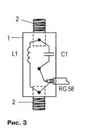
The installation was carried out on a standard getinax frame with a diameter of 16 and a length of 23 mm. Coil L1 is wound with PEV-2 wire with a diameter of 1 mm. The winding pitch is 3 mm, the number of turns is 3-4 (to be specified during the setup process). Bronze threaded rods 2 with M8 threads are pressed into the ends of the frame 1 (Fig. 3), which serve for fastening the emitter and the magnetic base of the antenna. These studs have additional fastenings in the frame in the form of bronze transverse studs, to which the leads of the ACS elements are soldered. On the side surface of the frame there is an additional insulated support contact, which also serves for mounting the elements.
The capacitance of capacitor C1 was selected experimentally. Was first installed variable capacitor small capacity with an air dielectric, which was later replaced by a permanent ceramic one. Capacitors KD-1 or KT-1 and similar ones with low or zero TKE and a rated voltage of at least 250 V are suitable. This is necessary even when using VHF radio stations with a transmitter output power of no more than 10 W.
After the final setup of the ACS, the coil terminals should be firmly secured to the frame, and all joints of the parts and the power cable should be well soldered. The capacitor must be coated with a layer of good moisture-resistant varnish, and the parts of the entire device must be well protected from moisture penetration.
In Fig. Figure 4 shows a graph of the antenna SWR as a function of frequency, Fig. 5 - a fragment of her appearance.


The antenna has been used with a mobile car VHF radio station for more than two years. During the initial check of its work, several dozen two-way radio communications were established with correspondents located in different points of our region, on different distances and height relative to the location chosen for the experiment. Most correspondents noted an increase of about one point in the signal level (as measured by the S-meter) compared to the quarter-wave GP antenna used in this experiment.
You can make such an antenna yourself, if you have a suitable ring magnet and a metal spring wire of a suitable diameter with good conductive properties for making the emitter. The metal base can be turned on a lathe by drilling an axial hole in its center for attaching the automatic control system.
Multi-element vertical antenna at 144 MHz
Readers are offered a description of the design of a multi-element antenna in the range 144...146 MHz. Its advantages are its original design and low weight. The antenna is placed inside a telescopic fishing rod and is convenient to take with you, for example, on a country trip, to the country house, etc. Making the antenna requires only a few hours of free time. Of course, it can also be performed in a stationary version.
As can be seen from Fig. 1, the antenna consists of four half-wave vibrators 1, located vertically, with power from the end through a short-circuited quarter-wave matching line-transformer 4. Phase-shifting elements 2 ensure in-phase activation of the vibrators. The antenna has vertical polarization and a circular radiation pattern.
The antenna design is shown in Fig. 2. The author placed it in a part of a plastic rod 4.5 m long. In the figure, for easier reading, the individual elements (knees) of the rod are shown as separate tubes. In fact, they naturally fit tightly into one another, without requiring sealing.
The transformer is made of copper wire with a diameter of 2 mm. To increase the rigidity of the structure, the wire is soldered to three spacer plates 3, made of one-sided foil fiberglass. The foil in the middle of the plates is removed, leaving only at the ends, in places where it is soldered to the wire. You can use spacers of a different design and from a different insulating material. A thicker wire is also suitable for the matching line. However, it should be remembered that the ratio of the distance between the transformer conductors to their diameter should be 8:1.
Each phase-shifting element of the antenna is a short-circuited quarter-wave section of a two-wire line - a loop. To reduce their size, they are rolled into coils. To make each loop, take a piece of PEV-2 wire with a diameter of 1.4 and a length of 1040 mm, a mandrel made of dielectric material (fluoroplastic, plexiglass) with a diameter of 9...10 and a length of 75 mm. The wire is folded in half and, starting from the middle of the mandrel, wound in different directions turn to turn. The ends of the winding wires are passed through through holes pre-drilled at the edges of the mandrels, cleaned and soldered.
The material for the vibrators is an antenna cord with a diameter of 2...3 mm (for a stationary antenna, copper wire of the same diameter is used).
The individual antenna elements are connected to each other by soldering in accordance with Fig. 1.

It is advisable to choose a fishing rod as rigid as possible and with such an internal diameter that all antenna elements can fit inside. In the thinnest bend, the antenna cord is attached using a fishing line with a diameter of 0.7 mm or a suitable elastic cord (Fig. 2).

An HF connector is built into the base of the rod. The connector is connected to the matching transformer with a short piece of coaxial cable (50 or 75 Ohms). The central conductor of the cable is soldered to the side of the transformer to which the antenna sheet is attached. The cable braid is soldered, respectively, to the opposite one. The connection points of the power cable to the transformer are selected according to the minimum readings of the SWR meter. Measurements are carried out with all foreign objects as far as possible from the antenna.
It is advisable to set up a stationary antenna at the place where it is permanently installed. In addition, the antenna should be grounded at the base of the matching transformer jumper, and foam cubes should be placed on its surface to eliminate the “rattle” effect (Fig. 2). If the rod is not rigid enough, you should use additional stretchers from a nylon cord, securing them in the area of the second (third) knee.
Chinese collinear VHF antenna for fixed installation. Judging by the reviews, the antenna is not bad.
The autopsy showed that, if desired, such a structure can be made independently.
First, let's look at the stated characteristics

The delivery set includes an antenna, counterweights, a metal tube and brackets for installation on a mast

Installation instructions

Complete photo

Now comes the fun part. I unscrew the star bolt and take out the antenna elements from the plastic pipe. Photo clickable

Phase shift coil

Matching circuit at the base of the antenna. I wanted to believe that the reel was wound on fluoroplastic, but it was still polyethylene. Protection against static is ensured by the fact that the antenna elements are grounded DC. The central core of the cable is connected through a capacitor

The antenna arrived with the capacitor terminal sealed off from the coil. I had to solder

The most difficult element to manufacture

Counterweights in the amount of 6 pieces


As the SWR measurement showed, the antenna is perfectly tuned. The SWR value at the boundaries of the 2m and 70 cm ranges does not exceed 1.2, in the center - 1.


