Electronic volume control with remote control. Audio amplifier control unit with ladder volume control and remote control How to make a remote control for a car amplifier
The motorized potentiometer is not new for a long time; there are even ready-made devices on sale. The price for it can be said to be “cosmic” and is beyond the means of many radio amateurs like me! 🙂
The idea itself is very interesting, because such a connection has many advantages - there is no interference from adjustments in the sound, it can be easily connected to a remote control, for remote control, the device itself can be used anywhere, replacing a regular potentiometer with it!
But in addition to the advantages, there are also disadvantages - For direct connection of the potentiometer to the shaft, only a stepper motor is suitable; for a regular one, a gearbox is needed! During adjustment, the sound of the motor will be heard, the motor must be controlled...
However, despite these disadvantages, there are still many benefits from this type of regulator, and I will further tell you how I implemented it!
It all started with the fact that I had accumulated a lot of different motors, stepper and conventional:
I needed to adapt them somewhere)) I didn’t touch the steppers, I’ll need them for other purposes, but I decided to twist the regular ones with a potentiometer to adjust the volume, since I’ve long wanted to adjust the volume with a remote control, for example, while listening to the radio at work or watching a movie on the computer.. :)
It will not be possible to connect the motor directly to the potentiometer; the motor may not have enough strength to rotate the potentiometer shaft, or, on the contrary, the motor will be so stupid that it will turn the shaft completely in a split second! =)
For this I needed a gearbox! But it was difficult to make the gearbox myself, I didn’t have the materials... That’s where my imagination came into play...
I went to a flea market, bought a cheap Chinese inertial machine for 10 hryvnia, removed from it a part that was very necessary for me and tried to connect it with a potentiometer:

As you can see, the motor was “embedded” in the very place where the inertial shaft stood, I removed the gear from it and put it on the axis of the motor, such a simple design came out!
The first tests were wonderful! The motor accurately turned the resistor knob, but it still rotated it relatively quickly... This is where I needed a control circuit, but more on that later...
Next, I used pliers to bite off the unnecessary parts of the axis of such a gearbox and, using a needle file, ground off one part “for a screwdriver”:

The mount turned out to be very durable, the Chinese did not skimp on material for the axle))
Actually what happened in the end:


The dimensions turned out to be relatively small... I secured the gearbox on a piece of PCB with hot glue (a cool thing, by the way, very useful around the house) and simply soldered the potentiometer with its body to the PCB!
Then I started working on the motor control circuit... I needed an indication of the volume level, since the device would be located inside the case, you need to see what position the regulator is in, it would be very bad to turn on the amplifier at maximum volume at night! 🙂
This is the diagram that came out:

The option is of course “crude”, but in practice everything works very well!
I'll briefly tell you how IT works:
A twelve-step indicator is assembled on transistors, which performs two functions - a volume level indicator (when the volume key is not pressed) and displaying the volume status for a couple of seconds after pressing the louder or quieter key and switching back to the level indication mode!
The motor control circuit itself is assembled on a “555” timer, which generates pulses to control the motor; communication with the motor occurs using an “H” bridge assembled on powerful transistors(which ones I had and used, but I only had TIP100 and TIP106). The transistors in the bridge that I used:

The driver always generates pulses, but in order to choose which direction to rotate the motor, we need to short-circuit one of the pairs of transistors by applying a one to any of the inputs (L or R)! If you connect an IR receiver to these inputs, as for example from the article about the previous “Amplifier with remote control”, then the volume can be adjusted with any remote control! I additionally placed two buttons on the case, but it’s not always possible to use the remote control! 🙂
You may need to use an additional amplifier for the level indicator input (LINE IN input), since on the mp3 player it did not have enough volume even at maximum to show the level, but from the computer it worked at full capacity...
Also on the diagram there is an approximate drawing of how to connect this system!
After assembling the circuit from scratch, I decided to first make everything with a body kit... This is what my “H” bridge and the whole device looked like:


It’s scary, of course, I don’t argue, but it works =))))
Later I made a printed circuit board for it, which I posted on the forum... I’ll say right away that I did NOT check it, I made it in haste and there may be errors in it! I will be grateful to anyone who checks it! 🙂
Despite the terrible appearance, the device works very well, smoothly adjusts the volume, and in combination with the remote control it turned out very convenient!
And finally, here's a video:
In the video it may seem that the volume is adjusted sharply, this is due to the fact that I connected the test amplifier (on the TDA8563) directly through the potentiometer to the computer! When connected via a tone block, the adjustment is much smoother!
First, the video shows an indication of the volume status, I close the “Louder” contact and the indication goes into the volume level mode, the LED strip fills, after a couple of seconds when I release the contact the indication returns to the signal level display mode (VU Meter). I turn on the amplifier, give a signal... For tests I used an amplifier based on TDA8563 and car speaker, which vibration turned everything on my table over! 🙂
I made an SE amplifier on the GU-50 and, as usual, the question arose about the volume control. I didn’t want to install a regular joint venture, and even remote control ( remote control) difficult to screw. It is expensive to buy a potentiometer from a well-known company APLS, and our dealers don’t have them.
I often saw on the Internet circuits of regulators based on resistive dividers; people call them “Nikitin regulators.”
Finally got around to trying it.
Attenuator circuit
The schemes presented in various sources had an adjustment step of 1 or 2 dB, and a maximum signal attenuation of 63 or 127 dB.
I decided to make an intermediate option with a step of 1.5 dB and an attenuation of 94.5 dB. Resistance 10 kOhm for tube amplifier Not enough, recalculated to 33 kOhm. It turned out to be 6 stages with resistors of the following values.

Various websites offering regulator designers write about the criticality of the resistors used in the divider. It is strongly recommended to use a 0.5% series, or at least 1%. I have enough resistors and I simply selected those closest to the calculated ones, paying special attention to the symmetry between the channels. Example: according to calculations, a resistor of 9.638 kOhm is needed, I selected 9.653 and 9.654 (for 2 channels).

The requirements for the relay are also not poor. I took a relay from an old mini telephone exchange, an Alcatel relay for 24 volts with 2 groups of contacts.
Well, they just exist.

Functions of my control unit
In terms of functionality, the volume control has evolved into a control unit with the following capabilities:- Remote control via IR
- Volume adjustment
- Turn on/off the amplifier
- Switching 4 inputs
- switch 2 speaker systems
- Switching indicator mode (output voltage/anode current)
- Delay on anode voltage switching on
- Forced on/off of anode voltage from the remote control
Control unit diagram
When developing the circuit, I wanted to make the relay control static, without high-frequency circuits. Registers are used for this, and the display circuit has already been used in my previous designs. The microcontroller met the resources PIC12F675.I wrote the program in assembler from scratch, without other people's inserts. The operation of the device is quite simple, we measure the voltage at the analog inputs (AN0, AN1), and depending on their value, we turn on the necessary relays. At the same time, we listen to the GP3 digital port for the presence of a message from the IR remote control. We expose the data to the GP2 output, and strobe the data through the GP4 and GP5 ports into the required pair of registers.
For each bit change, we write 2 bytes sequentially. Chains R25, C8, R28 filter high-frequency noise when writing to registers. Recording time 192 µS.
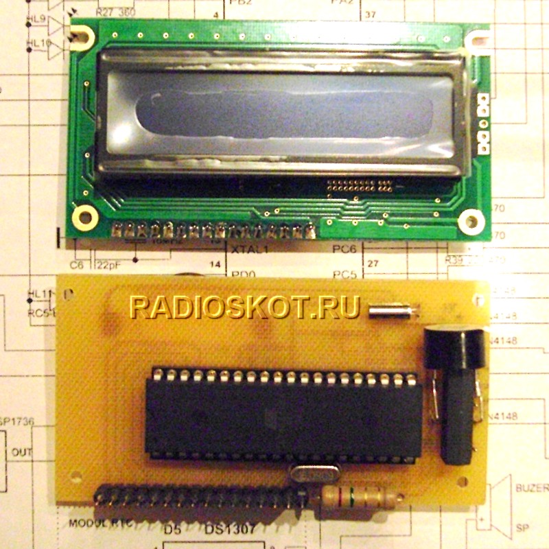
BU design and details
Structurally, the device is divided into two parts.The display unit, on which the controller is installed, is located on the front panel.

Relay module located near the inputs.

Printed circuit boards are made using LUT technology. On the divider board, the top layer of foil is left and used as a screen.

In the design, you can use a relay for a different voltage, respectively, connecting it to a different power supply. The transistors can be replaced with similar ones, but it must be taken into account that the KT972 has a built-in diode. IR23 registers can be 155, 1533, 555 series, imported 74S374 or, if the board is changed, IR8 155 series, etc. A feature of IR23 is its high load capacity.
I used the KRT-30 IR receiver. You can use any other brands, the main thing is that the modulation frequency of the remote control matches the frequency of the receiver, otherwise the range of the remote control may be greatly reduced.
power unit may differ from what is indicated. In my case, the standby voltage of 15V is stabilized at 12V, it is also used to power the display unit, and 24V is taken from the main ultrasonic transformer. The amplifier turn-on relay is designed for 12V and is powered by the standby power supply.
Separately, I will say about the power supply of the divider relay and input selector: it must be well stabilized, so the relay is more high voltage fits better (less current consumption).
The input and output selector switch is shown in the diagram as a biscuit switch; you can also use a variable resistor (similar to the volume control).
Regulator operation
After turning on the power switch, the amplifier is in standby mode, with the indicator showing “--”.To turn it on, you need to turn the volume knob or change the position of the input switch; the indicator displays the attenuation value in dB “32” (for example, corresponds to the position of the volume control).
The anode voltage relay turns on after approximately 70 seconds. Next, we adjust the volume, switch inputs, i.e. we manage as we wish.
The following functions are available from the remote control:
0 - power on/off
1 - volume [+]
2 - volume [-]
3 - switching inputs in a ring [+]
4 - switching outputs
5 - switching indicator mode
6 - switching inputs in a ring [-]
7 - mute button
8 - turn off / turn on the anode
9 – not used
Remote control training
Constant use of the previous design revealed a lack of attachment to a specific remote control, so here I made a learning remote control.You can use remote controls of popular protocols NEC, RC-6, RC-5.
With the device completely turned off, set the volume to maximum attenuation and the switch to position 2/4 (maximum).
Turn on the device, within 3 seconds you need to press any key on the remote control.
If the remote control is suitable, then “H0” is displayed on the indicator - you are asked to select the first key (from the list above), press it.
The unit accepts the code, “H1” is displayed on the indicators, etc. The number is the function number from the list. Unnecessary functions can be blocked by any buttons already in use.
If within 3 seconds after turning on a key on the remote control is not pressed or the remote control does not comply with the protocol, then the device goes into standby mode.
When the amplifier is turned on, the initial settings (volume, inputs, outputs) are taken from the position of the knobs on the front panel.
When programming, you can safely press the buttons for 1 second or more (repetition is not processed).
If desired, having read the data from the controller's non-volatile memory with the programmer, we will see the key codes - the two most significant bits of the device code.
Simplified version
For those who only need a volume control, here is a simplified diagram.You can program two remote control buttons without an indicator. We switch SA1 to the open state, the volume control to the maximum attenuation position, turn on the power, and press any button on the remote control for 3 seconds.
If the remote control is suitable, then when SA1 is switched, all relays remain turned off (maximum attenuation).
We program the buttons themselves, press any unused button once, and then
1 - volume [+]
2 - volume [-]
Now turn off the device, or press any key on the remote control 7 times. All buttons are programmed.
results
I was completely satisfied with the operation of the regulator; the volume is adjusted smoothly and in small steps. In the headphones you can hear the relay switching (a faint rustling sound only at the moment of regulation), in the speakers the regulation is practically inaudible.The indicator shows the attenuation in decibels, which is very practical.
The measurements showed a completely linear frequency response, no distortion of the signal shape, the attenuation error over the entire control range does not exceed 0.25 dB, and the asymmetry across the channels is extremely small.
The device was successful.
Files
The archives contain the following files: circuit diagrams, printed circuit boards (for the complete circuit), MK firmware (NEC protocol), MK firmware (RC-6 protocol), additional materials.▼
Organization volume control in high-quality equipment has always been an important and not simple issue. The potentiometer used for this must have high channel identity (for paired potentiometers), good wear resistance, and the absence of extraneous sounds (rustles and crackles) during adjustment. Today, conventional variable resistors are being replaced by biscuit switches, relay circuits, or integrated circuits. With significant cost and complexity, such options, while solving some problems, give rise to others. Therefore, many lovers of high-quality sound still prefer “old-fashioned” potentiometers.
Having set the goal of finding a high-quality potentiometer for your amplifier, you will definitely and quite quickly come across the company’s products ALPS. Indeed, their products are used in expensive devices and have high performance at a reasonable price. ALPS produces both conventional and motorized potentiometers. It is the latter that allow you to adjust the volume using remote control. You just need to connect the control circuit.
This article presents a circuit that allows remote control of motorized potentiometers. ALPS, as well as switch the amplifier’s five inputs using a standard remote control operating using the RC-5 protocol.
One chip.
Apart from the supply voltage stabilizer, the circuit contains only one microcircuit - this ATmega microcontroller from Atmel, which is responsible for decoding RC-5 signals, generating signals for motor control and input switch relay control signals.
Schematic diagram devices is shown in the figure:

click to zoom
The scheme is quite simple and detailed explanations does not require. Let us dwell only on some important points.
Ports PD2-PD6 via connector K3 can be used to control the input switch relay preamp.
The pins of the PC and PB ports are connected in parallel to increase the output current. They are used to control the potentiometer drive through connector K1. The maximum motor current according to the ALPS documentation is 150 mA. The maximum current of the microcontroller port according to Atmel documentation is about 40 mA. By paralleling 6 outputs, we can get a control current of more than 200 mA.
To indicate engine rotation, LED D1 is turned on parallel to it. Here you need to use a two-color LED and the color of the glow will make it clear in which direction the engine is rotating. If desired, it can be output to the front panel of the amplifier.
The structure can be powered from a separate transformer, which is connected to connector K5. Or constant voltage from the power supply of the amplifier itself. In this case, voltage is supplied to the board through connector K4, and elements B1 and C10-C13 do not need to be installed.
Design.
The figure shows the arrangement of elements on the device's printed circuit boards:

The design is divided into two parts for easy placement in the amplifier case. The motorized potentiometer itself is located on one board. This board is mounted in close proximity to the front panel of the amplifier.
The second board contains the power supply, microcontroller and other elements of the device. It is advisable to place this board in the amplifier housing as far as possible from the audio circuits and, if possible, shield it to reduce radiated interference.
The IR signal receiver must also be placed on the front panel of the amplifier, connecting it to the board with a three-wire cable. If the cable is long, to avoid unstable and false alarms of the receiver, it is necessary to duplicate capacitors C2 and C3, soldering them directly to the terminals of the receiver.
All connections of the structure are made by connectors, which are connected to each other by cables with the appropriate number of cores.
The potentiometer PCB provides contacts for connecting the signal cable shield and the motor control cable shield if necessary.
A photo of the finished structure is shown in the figure:

click to zoom
The signals for the transistor control keys of the input switch relay are removed from connector K3. To switch inputs on the remote control, use the number buttons 1...5. This way you can directly select the desired input. To switch inputs sequentially on the remote control, use the channel up/down buttons.
Important note.
The author tested his development with a remote control from Philips devices. It is clear that not every home has products from this well-known brand, so attempts were made to check the compatibility of other remote controls. I found a universal EuroSky 8 remote control (it’s black in the photo on the right):

This remote controlled well various devices in the house, but when it was programmed to work with audio devices, errors were observed when practicing auxiliary functions. It turned out that some remote controls do not work correctly with the RC-5 standard.
The editors of the Elector magazine carried out modernization software of this device in order to minimize errors when working with different remote controls from different manufacturers. Tests performed with the Philips SBC RU 865 universal remote control showed excellent performance. With others universal remote controls The remote control shouldn't have any problems either.
If you have a remote control tester, you can check if your remote control complies with the RC5 standard using the table below:

Here, as an example, are the incorrect codes transmitted by the EuroSky 8 remote control. The right column shows the correct command codes.
The article was prepared based on materials from the Elector magazine.
Happy creativity!
Editor-in-Chief of Radio Newspaper.
With the development and improvement of microcircuits for audio amplifiers (both preliminary and final), there is a desire to modernize control. The best way to do this is to use a controller. This project interested me very much in terms of functionality; the author of the controller circuit and the firmware itself put a lot of effort into bringing the control program to perfection (for which many thanks to him!). Next, I copy the author’s description with minor abbreviations.
Schematic diagram of the main unit
Microcontroller controlled preamplifier Atmega16 It is built on a modular principle, that is, everyone can create individual modules according to their wishes and preferences. This especially applies to output power amplifiers, power supplies, and speaker protection. In this material we will look at the input module on the chip TDA7313 and a processor control unit. Chip TDA7313 is included according to the standard scheme and has no special features. The unit is powered by a +9 Volt power source. This block has no more features. Files printed circuit board this and other modules archived on the forum, there are also schematic diagrams for connecting a keyboard, final amplifier and power supply.
Main module parameters:
1. Volume adjustment (16 levels);
2. Gain adjustment (4 levels);
3. Bass tone adjustment (16 levels);
4. HF tone control (16 levels);
5. Adjustment of the balance of the front speakers (16 levels);
6. Adjustment of the balance of the rear speakers (16 levels);
7. LOUDNESS - On/off loudness;
8. MUTE mode;
9. STANDBY mode;
10. Show time in mode MUTE And STANDBY and also after 10 seconds, when there were no keystrokes or other control inputs;
11. Control of all functions from the keyboard, remote control (RC) The remote control operates according to the RC-5 standard, as one of the most common;
12. Control using the Valcoder (encoder);
13. Monitoring the temperature of radiators or internal temperature in the case via two channels based on sensors from DALLAS DS18x20. When the set control temperature is exceeded, the cooling fan turns on.
The module uses mainly SMD elements. Microcircuits in DIP packages. The VD10 diode is installed on the opposite side of the board. The amplifier is controlled using a keyboard, encoder and remote control. You can use any remote control that works according to the standard. The keyboard is built in the form of a matrix of 12 buttons (4x3):
INPUT1- selection of 1 channel;
INPUT2- selection of channel 2;
INPUT3- selection of channel 3;
LOUDNESS- enable/disable loudness mode;
MUTE- turn off the sound (the shutdown occurs smoothly, not abruptly). Pressing again turns on the sound;
STANDBY- turn off the amplifier. The power amplifier and its power supply are turned off, the processor module operates in standby mode;
MENU- a button to enter the additional menu, in it you can set Extra options, such as time, date, response temperature of radiator control temperature sensors. Pressing this button again in this mode returns to the main amplifier control menu without saving the parameters. In order for the new parameters to be saved, you need to click on the button SET.
SET- as stated above, this is saving the new parameters entered in the submenu. Basically, when you press a key SET You can see the temperature of the radiators, information is displayed within 3 seconds.
UP/DOWN- move to the previous/next menu item or submenu;
LEFT/RIGHT- decrease/increase the corresponding parameter, which is displayed on the indicator.
The main buttons are processed by the program almost instantly, but pressing and responding to the button STANDBY requires pressing for approximately 3 seconds. Buttons MUTE And LOUDNESS about 1 second. This is done to prevent activation when these buttons are accidentally pressed, especially if the remote control is used. The main menu of the amplifier control program consists of the following items:
Volume(Volume)
Attens(Gain)
Bass(LF tone)
Treble(HF tone)
Balans F(Front speaker balance)
Balans R(Balance of rear speakers)
The key also works in this mode SET, when pressed, temperature values from the sensors are displayed for 3 seconds. When you press the button MENU we will be taken to an additional menu to set the time, date and maximum temperature parameters for temperature protection to trigger. This menu consists of the following items:
"Set Time: Hour" (time setting - clock),
"Set Time: Min" (time setting - minutes),
"Set Time: Sec" (time setting - seconds),
"Set Date: Day" (setting the date - day),
"Set Date: Months" (setting the date - month),
"Set Date: Year" (setting the date - year),
"Set MAX DS18x20" (setting the thermal protection response temperature).
In this mode, movement through the menu is carried out using the keys UP/DOWN(and the remote control keys), and parameter adjustment using the keys LEFT/RIGHT(and encoder). At any of the points, if we press the key MENU, then we will return to the main menu without writing new values, and if we press the key SET, then saving the entered parameters. For convenience, the author provided firmware in English, Russian and Ukrainian. As an option, I decided for myself to control only the remote control, so I don’t want to assemble and install the encoder and keyboard. The payment that the author provided was made for himself, so he decided to make his own.

I finished assembling the preamplifier - everything opens and is adjustable. Since there are no sensors, they are not defined (in the form of dashes in standby mode). I built my board for SMD, but the processor is in a Dip package, so the board fits it according to the size of the indicator - this is the main reason why I don’t put the board in Lay.
The second board will be the pre-amplifier itself on the TDA7313. The third board is a power supply control module and standby mode. Here is a photo:

It's time for testing. Plays great! I'm pleased with the depth of adjustment of the bass and treble, the bass is soft, the high-pitched tweeters are so loud (although with OM it will certainly be more fun), I especially liked the loudness compensation with its very impressive rise in the low frequencies. In general, I can only say one thing about the device so far - continuous advantages!

After driving for half a day, I did not find any flaws in the firmware, the operation of the remote control is clear, in general, if anyone decides to repeat this scheme, they will not regret it! Author of the scheme - Andrey Doinikov. Assembly and testing - GOVERNOR.
Discuss the article MICROCONTROLLER CONTROL IN ULF
Most often, in cascades of volume controls of high-quality sound reproducing equipment, variable resistors are used directly as regulators, allowing the signal gain to be gradually or smoothly changed. However, often in tube LF amplifiers step volume controls are used, made using fixed resistors and switches.
The simplest and most common circuit design solution for a tube ULF volume control when choosing smooth adjustment is to introduce a potentiometer with a variable voltage division coefficient into the input circuit, into the interstage circuit or into the negative circuit feedback amplifier By moving the slider of this potentiometer, the volume is directly adjusted. In this case, it is recommended to use variable resistors with a so-called logarithmic characteristic (type B characteristic) as an adjustment potentiometer to ensure a uniform change in the volume of the reproduced signal at different input signal levels.
If desired, the volume control with smooth adjustment can be replaced with a regulator with step adjustment. To do this, it is enough to make an appropriate replacement of the regulating element, that is, instead of a potentiometer, install a chain of series-connected constant resistors, the number of which and the ratio of their values determine the range and law of regulation.
When choosing a volume control circuit, one should not forget that the human ear has different sensitivity to signals of different frequencies and volumes. In practice, this phenomenon manifests itself in the fact that when reducing the volume of the reproduced sound signal The listener gets the impression of a change in sound timbre, which is expressed in an apparently significantly greater decrease in the relative volume of the components of lower and higher frequencies compared to mid-frequency signals. Therefore, in high-quality sound-reproducing equipment, fine-compensated volume controls are used, in which, when the volume is reduced, the necessary rise in the components of lower and higher frequencies is carried out to ensure equal loudness of perception. As the volume increases, the required rise in the edge frequency components decreases. The basis of fine-tuned volume controls is usually potentiometers with one or two taps, to which the corresponding RC circuits are connected.
Typically, the volume control is used to change the level of the ULF output signal with minimal introduced distortion. In this case, most often a variable resistor is used as such a regulator, connected either at the input of the amplifier or between the preliminary and final stages. Instead of a variable resistor, as already noted, a step regulator can be used, made on the basis of a switch and a cassette of resistors with different resistances. Simplified circuit diagrams of the simplest volume controls are shown in Fig. 1.
Fig.1. Simplified circuit diagrams of volume controls
To prevent the possibility of overloading the first amplifier tube with a large amplitude of the input signal, the volume control connection diagram shown in Fig. 1, a. In this case, the variable resistor is used directly as a load of the previous device. If the maximum amplitude of the input signal is small, a variable volume control resistor can be installed in the control grid circuit of one of the subsequent amplification stages, as shown in Fig. 1, b. The advantage of this connection is that it reduces the impact of external interference, since a useful signal is supplied to the regulator, already amplified to the required level.
The volume level in tube ULFs can also be adjusted using special cascades, which provide a change in the slope of the lamp characteristic. The principle of operation of such volume controls is based on the fact that when a lamp with a high internal resistance is used in the amplifier stage, the gain of such a stage will be proportional to the steepness of its characteristic (S). Therefore, when using a lamp with a variable slope characteristic, to change the gain of the cascade, it is enough to move the operating point to an area with a different slope value. The position of the operating point and, accordingly, the gain can be changed different ways, for example, by changing the bias voltage or voltage on the lamp screen grid. Simplified circuit diagrams of such volume controls are shown in Fig. 2.

Fig.2. Simplified circuit diagrams of volume controls with changing the slope of the lamp characteristic
It should be noted that the volume controls considered, which use the principle of changing the slope of the lamp characteristic, can only be used in the first stages of the ULF at relatively small amplitudes of the input signal (no more than 200 mV). At higher input signal levels, significant nonlinear distortion, caused by the curvilinearity of the dynamic characteristic.
To adjust the volume in low-frequency tube amplifiers, regulators are often used that provide compensation for low frequencies at low input signal levels. A schematic diagram of one of these regulators is shown in Fig. 3.

Fig.3. Schematic diagram of a volume control with low frequency compensation at low input signal levels
An input signal with a fixed level rise is supplied to the input of the cascade lower frequencies reproducible range. This level is determined by the resistance values of resistors R1, R2 and R3, which form the input divider, as well as the value of the capacitance of capacitor C2. From the output of the regulator, a feedback signal is supplied to the lamp grid circuit through a divider formed by elements R7 and C2. The higher the volume level, the greater the feedback. The resistance value of resistor R7 determines the ratio of the attenuation of low frequencies in the feedback circuit to the rise of these frequencies in the input circuit. Ideally, by selecting the resistance of resistor R7, it should be ensured that the attenuation of low frequencies in the feedback circuit is equal to their increase in the input circuit. In this case, the shape of the frequency response of the signal at the output of the stage will be close to linear. Shown in Fig. 3 element ratings are designed to use one of the triodes of the 6N2P lamp.
When the signal volume is reduced using potentiometer R6, the feedback value also decreases, but the fixed increase in low frequencies remains the same. As a result, the level of low frequencies in the output signal increases. At very low volume values, there is practically no feedback, and the cascade characteristic is determined only by the parameters of the chain R1, R3 and C2. At the same time, the rise in lower frequencies is maximum.
One of the disadvantages of this circuit is that the triode is connected before the volume control, so with a very strong input signal it can be overloaded. However, the signal from the input is fed to the control grid of the lamp through a divider, which, even at a frequency of 50 Hz, provides an attenuation of more than 4 times. As a result, this circuit can operate without distortion at an input signal level of up to 4-5 V. It should also be noted that the circuit in question is sensitive to the level of anode voltage filtering, so the use of the R8C5 filter in the lamp anode power circuit is mandatory.
When designing a tube ULF, radio amateurs often set themselves the task of including a cascade, with which they can adjust the volume remotely. The use of remote consoles with potentiometers placed in them in conventional regulators can hardly be considered a good solution, since most often such consoles are connected to the amplifier using long cables, which leads to very significant distortions. However, there are various circuit solutions that provide volume control at a distance, for example, by changing the control voltage direct current, with virtually no distortion. A schematic diagram of one of the options for a volume control with remote control is shown in Fig. 4.

Fig.4. Schematic diagram of a volume control with remote control
A distinctive feature of the regulator in question is the inclusion, instead of the cathode resistor of the amplifier stage triode, of another triode, which acts as a regulating element. When the value of the constant negative voltage supplied to the grid of the second triode changes, the value of its resistance changes. As a result, the depth of negative feedback for the first triode changes. So, for example, as the internal resistance of the second triode increases, the negative coupling increases, and the gain of the first triode decreases. In this circuit, an imported double triode of the ECC82 type can be replaced, for example, with a domestic 6N1P lamp.
In high-quality tube sound-reproducing equipment, volume controls with loudness compensation are widely used. The need to use such volume controls is explained by the fact that the sensitivity of the human ear changes depending on the frequency and volume of the perceived sound signal. For example, better sensitivity corresponds to the perception of mid-frequency components compared to higher and especially lower frequency components. Therefore, when the volume is reduced, the listener has a subjective feeling that the level of the components of the higher and lower frequencies of the reproduced range is simultaneously decreasing. As a result of research carried out in this area, certain dependencies were drawn up, which were called curves of equal loudness.
So that at different volume levels all frequency components of the reproduced signal are perceived equally, high-quality sound-reproducing equipment uses volume controls, in which, as the volume decreases, the necessary rise in the components of lower and higher frequencies is carried out, and with an increase in volume, the rise in the components of the boundary frequencies decreases. Such regulators are called loud-compensated or frequency-dependent. Naturally, developers strive to ensure that the characteristics of thin-compensated volume controls are as close as possible to equal volume curves.
The simplest option for constructing a frequency-dependent volume control is to combine the volume control directly and the tone control using paired variable resistors. Schematic diagrams of such volume controls are shown in Fig. 5, a and 5, b. Often, high-volume volume controls use potentiometers with one or two taps, to which the corresponding RC circuits are connected. A schematic diagram of one of the variants of such a volume control is shown in Fig. 5, c.

Fig.5. Schematic diagrams of simple loudspeaker volume controls
The current-compensated volume control can also have step adjustment. The advantages of such regulators, in addition to the absence of a potentiometer of the appropriate design, include the ability to select a significantly wider adjustment range. A schematic diagram of one of the options for the input stage of a tube ULF with such a regulator is shown in Fig. 6.

Fig.6. Schematic diagram of a thin-compensated volume control with step adjustment
Loudness compensation in volume controls can also be implemented using special filters. The schematic diagram of the regulator with a loudness filter is shown in Fig. 7.

Fig.7. Schematic diagram of a volume control with a loudness filter
In the circuit under consideration, the loudness filter is a double T-bridge, the transmission coefficient of which for the components of the middle frequencies of the reproduced range is less than the transmission coefficient for the components of lower and higher frequencies. In maximum volume mode, the potentiometer R4 slider should be in the upper position in the circuit, while the filter is short-circuited and does not affect the shape of the frequency response. To decrease the volume, the slider of potentiometer R4 should be moved down, which reduces the shunting effect of the upper part of this potentiometer on the filter. As a result, components of certain frequencies begin to pass through the filter in accordance with its frequency response. Since the components of the middle frequencies are attenuated by this filter to a greater extent than the components of the extreme frequencies, the change in the frequency response of the amplifier occurs according to a dependence close to equal volume curves. Potentiometer R4 must have a logarithmic characteristic (type B).


