How a subwoofer is made. We assemble a subwoofer with our own hands! Output power indicator
Introducing a complete subwoofer amplifier module based on the popular TDA7294 ASIC. This is the best microcircuit for UMZCH, in terms of power/price ratio. Therefore, they lose noticeably.
Features and functions of the circuit

- power amplifier on TDA7294 (70-140W)
- bass gain adjustment
- adjustable low pass filter (80-150Hz) switchable
- phase switch (0-180 degrees)
- infra-low pass filter (passive 3rd order 19, 25, 33 Hz to choose from)
- automatic on/off using the switch for this function (ON/AUTO mode)
- mono/stereo input with sensitivity 150 mV
- silent on/off system
- Dimensions of the board with parts are only 10x10 cm
Module diagrams
Power amplifier circuit diagram

The TDA7294 chip is a classic in home audio engineering. Simplicity, reliability and high repeatability: this is what persuades many to choose this particular TDA. It works both in bridged and single connection.
Schematic diagram of a low-pass filter

The input signal processing unit can work as a mono or regular stereo audio signal from the linear output of a DC or PC. The phase shift can be adjusted. The basis is operational amplifiers TL074 and TL062.
Schematic diagram of the subwoofer power supply

In addition to the power supply itself, which generates voltages of 2x12 and 2x33 volts, a speaker turn-on delay unit is shown here (transistor BC546 and 24 V relay).
Transformer selection
For normal operation The subwoofer PA module requires the connection of a powerful main power transformer and a small 12 V standby transformer. Recommended transformer (to ensure maximum power):
- Version 1 x TDA7294: 100W 2x24V for 4 ohms, 100W 2x30V for 8 ohms
- Version 2 x TDA7294: 200W 2x24V for 8 ohms, 200W 2x30V for 16 ohms
Subwoofer design
 Ready-made homemade subwoofer block
 All elements of a homemade subwoofer are assembled into a single module, which can already be used as a separate device or built into the box of a passive subwoofer, making it active. To do this, you can take a ready-made speaker from the old Soviet AC-90, removing unnecessary speakers and filters from it and moving the controls outside. Download the project files - .
SUBWOOFER WITH YOUR HANDS
Sooner or later, many people realize that there is no such thing as too much bass, and no matter how much they look for more powerful speakers, they still want more bass. There is only one way out - use a subwoofer. You can buy a good subwoofer, but not everyone has the extra $200 - $300. So we will make a subwoofer with our own hands!
First, let's solve the power supply issue: a good transformer, 150 watts, has the required bipolar voltage and there is no current lying around on the road, but I really don’t want to wind it myself. And it is not necessary. We buy electronic transformer for a standard voltage of 12 V and a power of 100 - 150 Watts and connecting to its output a ferrite ring K40x30x20 with a primary winding of 13 turns of PEL 1.2; with two secondary 28 turns of the same wire we have a bipolar voltage of 25 V.
Scheme DIY subwooferconsists of an active filter on TL082 (TL062) and the amplifier itself, assembled according to a standard push-pull circuit. To improve sound quality (and who said that bass is not critical to distortion?), there is a pair of field-effect transistors at the output. More details about the low-pass filter - calculation, diagram and drawings printed circuit boards. One of great options filter circuits for a subwoofer with a phase shifter are shown in the figure.

The subwoofer is powered by or from the abovean electronic transformer, or from a conventional transformer, with two windings of 20 - 30 V for a current of 3 A.

It should be noted thatelectronic transformers do not operate at low load currents, so thisDIY subwooferIt works in class A, which, as you understand, also has a very good effect on the sound quality. The current consumption of each arm must be at least 0.6 A. It is set with a trimming resistor of 1 k.
As an option, you can use the TDA7294 microcircuit, connected according to the diagram below, as an UMZCH.

Speaker for DIY subwooferwe take any low-frequency one, the more powerful - this sub produces more than 100 watts pure sine. Power supply +-30 V, with a maximum peak current consumption of up to 4 A. The measured harmonic distortion is less than 0.1%.

For body DIY subwooferWe use an old Soviet wooden TV, maybe a tube TV or a 3USTST.

We make a cut in the top center, and we get two side panels with halves of the upper part. That is, two letters G. We turn one of them over - the frame is ready, and the bottom will be used as the back wall. Caulk the joints with sealant and do not forget to make a bass reflex hole in the front with a diameter of 8 mm.More details about the calculation and manufacture of the case can be found on other resources. And read here practical detailed assembly example
Pavel Parygin
Kyiv
I probably won’t reveal much of a secret if I say that the small-sized speakers that are equipped in car audio systems do not provide good “bass” reproduction. One of possible ways The solution to this problem is also well known - to supplement the stereo system with an active subwoofer (an amplifier common to the right and left stereo channels with its own speaker, which reproduces low-frequency components of the sound range up to 200-250 Hz). But such an acoustic unit with an additional amplifier costs almost more than the entire stereo system taken together. That's why I decided to take on making it myself.
In order to make an active subwoofer in a car with my own hands, I purchased a 10-inch ALTRONIX E-RSW1039A low-frequency speaker (Fig. 1), two electronic kits for radio amateurs - an active signal processing unit for the subwoofer channel and a powerful single-channel low-frequency amplifier NM2034 ( as finished block BM2034), 5 m of special cable (ROCAR HIENDPCOFC SPEAKER CABLE) for connecting the speaker system, housing for electronics assembly (Z-4A), terminals, connectors, plugs.
Fig.1. ALTRONIX E-RSW1039A woofer
But first we had to start manufacturing a “closed box” type speaker system housing with a bass reflex (Fig. 2).

Fig.2. The design of the subwoofer housing is closed type with a bass reflex.
The useful volume of the body V, diameter d, length L of the bass reflex and other parameters were calculated on a computer using the JBL SpeakerShop program. The program performs all these calculations based on the characteristics of the speaker used (total quality factor Qts, resonant frequency Fs, equivalent volume Vas, etc.). In my case it turned out: d=60 mm, l=96 mm. For speakers of another type, these parameters will naturally be different, and the design acoustic unit necessary changes must be made.
The easiest way to make a housing for a car subwoofer at home is in the form of a round barrel, with a speaker built into one of the bottoms. In this case, both bottoms can be cut with a jigsaw from chipboard or multi-layer plywood (Fig. 3), and the cylindrical body is bent from a sheet of fiberboard.
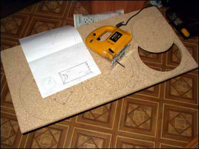
Fig.3. Both round bottoms of the body were cut out of chipboard with a jigsaw.
At first I doubted the strength of such a design and assumed to glue two layers, but after completing the assembly, all my doubts were dispelled, since the body turned out to be very rigid and with fiberboard in one layer. It turned out to be quite simple to bend a blank from a sheet of fiberboard into a cylinder. To do this, it is enough to steam it from the outside, ironing it through a wet hoe.
After the fiberboard sheet was bent, I glued the round bottoms with PVA and additionally secured them with staples using a construction stapler. The finished body was covered with carpet on the outside (glued and secured with staples) (Fig. 4).

Fig.4. The finished building is covered with carpet.
Finally, I glued in the bass reflex, attached an insert with terminals for connection to the rear panel, soldered the wires and installed the speaker in place. Everything turned out very well (Fig. 5).

Fig.5. Active subwoofer assembled.
There were no problems with assembling the electronics. Both sets include fairly detailed and understandable instructions, according to which everything can be assembled and connected easily and simply (Fig. 6).

Fig.6. There were no problems with assembling electronics from MASTER KIT kits.
The only thing I didn’t do according to the instructions was install a radiator with an area of 600 cm2 instead of the one recommended for the power amplifier chip central processor(Socket 370 connector) with a fan left after upgrading the computer. The replacement turned out to be quite acceptable.
And finally, I specially moved the electronics into a separate housing, although it would be more rational to place it in the housing of the acoustic unit, separating a special compartment for this. But I really wanted to turn all these knobs myself and adjust the subwoofer directly inside the car while listening to real music. That's why assembled amplifier I placed it in the glove box (Fig. 7), and additionally installed a separate power switch on its front panel.
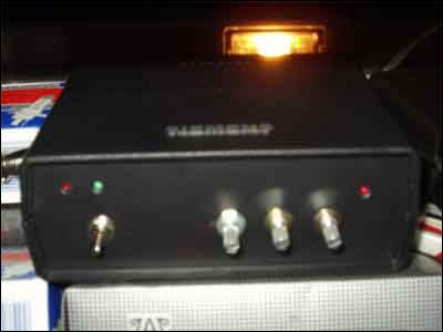
Fig.7. The electronic unit of the subwoofer is installed in the glove box, colloquially called the “glove box”.
A stereo system with a homemade car subwoofer sounds no worse than with a branded one, and costs several times less. But the main thing is that I made the subwoofer with my own hands!
Due to the fact that the BM2034 amplifier is no longer in production, Master Kit recommends using
From that article you will learn how to make an amplifier for a medium-power car subwoofer.
The presented amplifier, like many industrial amplifiers, lacks various protections. But this does not affect the reliability of the amplifier in any way. This device can work for a very long time if no one short-circuits anything.
To achieve a cutoff of about 100 Hz (all frequencies above are absent), a second-order filter is introduced into the circuit.
This is a regular Push-Pull converter, push-pull boost. The master oscillator is built on the TL494 chip.
Next there is a small driver using direct conduction transistors. This part discharges the capacitance of the gates of the field-effect transistors after the latter are closed.
As you know, if some voltage is applied to the gate of a field-effect transistor, in this case it is a control pulse, then the latter will open. And if you remove the voltage at the gate, the transistor will still remain open.
Therefore, some circuits are supplemented with a separate driver, which can turn off the transistor in time. Although many dedicated PWM controllers have a fairly powerful built-in output stage for this purpose, the TL494 is not one of them.
It is fashionable to use literally any PNP transistors in the driver. Our KT3107 also fits perfectly.
Field-effect transistors, as always, are n-channel - in this case IRFZ44, but others are possible. When selecting transistors, you need to pay attention to the documentation. The design voltage of the key must be at least 40 V, and the current strength must be at least 30 A. Ideal option keys will become 60 V with a current of 50-60 A.
The primary winding has 2 five turns, wound with a bundle of 5 wires of 0.7 mm each. The secondary winding has 11 turns, 6 cores of 0.33 mm each. Naturally, for each core there will be different winding data, so the calculation must be done independently.
The idle speed of the inverter turned out to be no more than 50 mA, and with a connected filter and amplifier it was about 250 mA, taking into account the fact that no signal was supplied to the amplifier input. Idle speed is minimal.
The amplifier works in class A-B, and the radiator needs to be quite large considering the power. Be sure to isolate the housings of field-effect transistors and amplifier microcircuits from the radiator using heat-conducting gaskets and insulating washers.
Attached files:
Homemade active subwoofer for home.
Hello, friends!
On this page I I’ll briefly tell you how to make an active subwoofer for an apartment or country house with your own hands based on a speaker for a car subwoofer. This design has been working in my city apartment for several years now and believe me, I really like the HOW IT SOUNDS!
Since childhood, I have had the impression that it is very difficult to make a correctly sounding speaker, and that to do this you need to be a great scientist in the field of calculations speaker systems and sound waves - still, homemade products will work somehow, and it is almost impossible to achieve at least any high-quality sound using such methods.
However, later I was lucky to meet at work one very interesting man, a certain Igor Mikhailovich Golubyatnikov, who had previously professionally installed audio systems in cars on special orders in a specialized auto audio center.
He told me that there is nothing particularly difficult in the design and manufacture of acoustic systems, and especially in the manufacture of a subwoofer, and that it is not so difficult, and most importantly, you can get a very good result. Inspired by his instructions, I went to the Mitinsky radio market (in Moscow) and purchased a 12-inch diameter car subwoofer speaker there. FBX-12 from Power Acoustik . Alas, for some reason I didn’t think of taking a photo of the speaker itself and the housing parts during the construction of the subwoofer. The following photo is taken from some other site:

This speaker came in a neat wooden box with metal heels on the corners,

Which, after tearing out all the partitions from it, is now ideal for storing cans of paint:

Printed on the lid of this box specifications dynamics:

Design.
On the advice of Igor Mikhailovich, a circuit with a bass reflex was chosen. The hull calculation was performed in the program"GBL SpeakerShop ", data for the speaker was included on the package insert. According to calculations, the required volume of the subwoofer housing was 120 liters.
The body is made of chipboard (bare, gray on both sides) 16mm thick. Each wall of the housing around the volume behind the speaker is made of such chipboard in three layers. The layers are glued together with PVA glue and additionally secured with self-tapping screws (so as not to wait for the glue to dry). In total, the wall thickness was almost 5 cm. The case is completely sealed, glued, and the cracks are “sealed” with PVA glue diluted with sawdust left over from the manufacture of the case walls.
The speaker itself, except for the mounting screws, is glued in with silicone sealant.

The bass reflex is made in the form of a slot, one wall of which was movable at the manufacturing stage to adjust the length of the bass reflex channel. After adjustment, the excess part of this wall was cut off, and the wall itself was glued into the body. Next, sanding, painting - and the body is ready:

Since the subwoofer is active, it was also necessary to provide space for an amplifier. Therefore, the case, in fact, is not just a hollow box, but consists of two compartments - a large one behind the speaker itself, and a small one in the back (10 centimeters thick). The compartments are separated from each other by a sealed partition, also made of three layers of chipboard. The wires from the speaker to the amplifier compartment pass through hermetically sealed seals.
Electrical part.
The speaker contains two independent windings, each with a resistance of 4 Ohms. Therefore, a circuit of two amplifiers was chosen, each of which operates on its own speaker winding, independently of the other. These amplifiers are combined only by the input signal (and supply voltage, of course).
Here is a schematic diagram of the amplifiers (click to enlarge):

In fact, a very good microcircuit was used as the amplifiers themselves -TDA7294, which is a ready-made powerful (up to 100W) audio amplifier with an acceptable bipolar supply voltage of up to +/- 50V and an output current (to load) of up to 10A. The output stage of this microcircuit is built on field-effect transistors; the microcircuit has a low noise level and low distortion of the amplified signal.
The input signal is supplied to the inputs of these microcircuits without any conversions, restrictions or frequency cuts. This is due to the fact that my home audio system uses DVD -player, aka FM tuner, aka amplifier - Onkyo DR-L50 . Here is a detailed article about this unit on the website iXBT (who is interested): .
This device has a special subwoofer output, which outputs a specially prepared low-frequency signal, and in which you can adjust the volume independently of the other channels of the player, and thereby adjust the operation of the subwoofer in relation to the mid and high frequencies reproduced by the rest of the audio system.
The amplifiers are powered from a single bipolar power source, made according to a standard circuit - a toroidal transformer with two identical secondary windings of 25 Volts each, a bridge rectifier (ready-made rectifier module) and electrolytic capacitors. The total capacity of these capacitors was chosen with a large margin (it could have been much less). If you turn off the power, the subwoofer continues to operate on these capacitors for several tens of seconds (not at full power, of course).
The amplifiers themselves are each mounted on a small board,


And the entire circuit - in its entirety - is on the back wall of the amplifier compartment of the subwoofer housing (there is only 1 layer of chipboard):


All power wires have a cross-section of 2.5mm 2 - to transmit maximum power to the speaker. The amplifier microcircuits are mounted through special windows in the rear wall on radiators facing the rear surface of the case. Radiators - from power thyristors at 320A (very redundant in size, but they look good):

In the photo just above you can see that there is another board in the circuit (with two orange radiators), which does not seem to be shown on schematic diagram. This is due to the fact that the amplifier chips TDA7294 have separate outputs (or rather inputs) of power supply (for weekends field effect transistors) and separate low-current power outputs (inputs) to the rest of the circuit. Initially, it was planned to supply the full power supply voltage directly from the source to the power supply terminals, and stabilized +/-15V power to the low-current supply terminals through the same board with orange radiators (this is a bipolar step-down power stabilizer). However, such a circuit did not work, and moreover, two amplification microcircuits TDA7294 were thus completely spoiled. I had to redo the amplifier boards again - connect both the low-current and power outputs (inputs) of each amplifier chip together (to each other). Thus, the need for this step-down stabilizer (board with orange heatsinks) disappeared - it was left for the sole purpose of powering the “On” LED. (in the circuit diagram shown, this LED is connected directly to the full supply voltage through a corresponding resistor).
In addition to the two damaged amplifiers, there were other problems when assembling the circuit. The photo below shows the poor placement of the input signal wires to the amplifiers (note the thick white wires running from the input jack to the amplifiers themselves - in fact, this is a shielded signal wire in a protective white cambric). Compare the location of these wires in the photo above and below this text:


This seemingly insignificant detail led to the fact that even with the input short-circuited (on the feed socket sound signal) the background of the network frequency of 50Hz was clearly heard from the speaker.
The circuit wires were redone to create maximum symmetry (pictured above). After this, the 50Hz background completely disappeared from the speaker.
Since the manufactured subwoofer turned out to be quite bulky, it was suspended from the ceiling on anchors - so as not to take up useful space near the floor surface:

A few words about setup.
On the advice of Igor Mikhailovich, before the speaker was glued into the housing, it was first “stretched out”. To do this, the speaker was supplied with mains voltage through a step-down transformer at 15 volts of sufficient power, and for several hours the speaker membrane oscillated at a mains frequency of 50 Hz. At the same time, the speaker was put into a closet, in which it was additionally littered with various pillows and blankets - so that it could be heard as faintly as possible.
This was done so that the speaker membrane suspension system would “break in” (“warm up”) (the speaker is new) and in the future would not change its rigidity properties much during operation (the strongest change in the properties of the membrane suspension of a new speaker occurs at the initial stage operation of this speaker). If this is not done, then since the phase inverter adjustment would have been made for the properties of the new speaker, then after it has been “breaking in” (“warming up”) during operation, its properties could have changed, and the phase inverter adjustment could have gone astray.
Then Igor Mikhailovich gave me a special audio disc on which 60 tracks were recorded - a regular sine wave, starting from 20 to 80 Hz (in 1 Hz steps). By listening to these tracks one after another and in selective order at the same volume, you can adjust the bass reflex so that the sound volume of these tracks (i.e., the volume of playback of different frequencies) (by ear) would be approximately the same (so that there is no pronounced resonances). This is exactly how the bass reflex of this subwoofer was configured.
I must say that when everything was done, configured and glued, I was very pleased with the results of my work. It was experimentally found that to create a sufficiently “powerful” bass using this subwoofer, relatively little electrical power is required, and the vibrations of the speaker membrane are barely noticeable. To create a similar sound, say, using speakers from music center, they must be supplied with significantly greater electrical power, and the membranes of their speakers, at the same time, fluctuate very significantly.
If the volume of the audio system with this subwoofer is increased, everything around “starts to move”, the glass in the windows begins to ring, the floor begins to tremble, objects on the table surface begin to move spontaneously. I especially like to show my guests the beginning of the Ice Age cartoon, namely the moment when, at the very beginning, this wonderful squirrel hammers a nut into the ice, after which the rest of the plot of the cartoon begins. If you turn it up louder, the sound in this place turns out to be truly “amazing” - in the literal sense of the word. At such moments, only one thing upsets me - the understanding that there are neighbors around me, and that their patience may someday end...


