Working with 1602 graphic display in arduino. LCD WH1602B from Winstar. LCD screen control via I2C bus
Had arrived Arduino Nano, a kit arrived, containing a breadboard and an LCD display. The display on the board says - 1602A, below - QAPASS. I started sculpting the first device, and of course, I wanted to display information on the display, and not blink LEDs.
Google helped, told me that this is a character display; If you don’t distort it, then most likely ASCII characters are available - numbers, Latin, some of the basic characters.
The following materials helped to launch the display: Driving a character type LCD from a PC printer port; How to connect Arduino with a character LCD ; Pwm Servo Driver Motor Control PDF.
The display is quite common, and shields have already been invented for it - there are options with SPI, like, and/or with I2C, and the Internet is full of recipes for these cases. But I only had the original 16x2 display and the Arduino to which I wanted to attach it.
The display has a mode of operation and data transmission in nibbles, 4 bits each, while the low-order bits of the bus are not used. Connecting only half of the data bus is described in many places, and I did not figure out how to connect the display and work with it over 8 lines. I'm quite happy with how it works.
Good description of displays of this type I found it here - http://greathard.ucoz.com/44780_rus.pdf. And here (http://arduino.ru/forum/programmirovanie/lcd-i2c-partizanit#comment-40748) is an example of specifying a character generator.
Connection
My display came with unsoldered contacts. From the beginning I wanted to solder the cable, cut 16 wires with duponts, and cleaned them. And then I dug around in the whale and found a DuPont comb for soldering to the board. From there I broke off 16 contacts and soldered them.My display looked something like this (before soldering the contacts):
First I connected pin 15 (A) to +5V, 16 (K) to ground, and made sure that the backlight worked. In general, it is correct to connect the cathode to ground through a 220 Ohm resistor, which is what I then did.
Then I connected the ground (1) and power (2). Arduino can be powered from USB, from a stabilized voltage of 5V and from an unstabilized 6-12V, the highest voltage is automatically selected. Now the Arduino is powered from USB, and I was wondering where to get 5 Volts. It turned out that 5V is on the Arduino pin, where external stabilized 5V is connected. Or rather, it turned out to be 4.7V, but that was enough for me.
After connecting the power, if everything is fine, then the top row lights up with solid rectangles of familiarity.
Then we connect the contrast potentiometer (pin 3 V0). We throw one of the extreme terminals of the potentiometer to the ground, the second to +5V, the middle one to pin 3 of the display. A 10K potentiometer is recommended. I had 50K from whale, I used it first. The adjustment was only on one edge; it was necessary to catch the desired contrast very subtly. Then I found a similar one at 5K in another whale and installed it. The setting stretched from one edge to half a turn. Apparently, you can take an even smaller potentiometer. 10K is probably recommended so that the circuit consumes less. Yes, I had to do a little soldering; I soldered wires with duponts to the terminals of the potentiometers.
Test sketch
We take the test sketch from the examples from Arduino Studio - "C:\Program Files (x86)\Arduino\libraries\LiquidCrystal\ex amples\HelloWorld\HelloWorld.ino", just need to change the contacts to ours - LiquidCrystal lcd(7, 6, 5 , 4, 3, 2);In principle, this sketch also contains a description of what to connect where. You can connect it as indicated there, then you don’t need to change anything at all.
// include the library code: #include
It turns out something like this: 
By the way, the display that came into my hands does not work without backlighting. I mean, it works, but you can hardly see anything.
1602A Display Contacts
| # contact | Name | How to connect |
|---|---|---|
| 1 | VSS | GND |
| 2 | VDD | +5V |
| 3 | V0 | Contrast - to the middle terminal of the potentiometer |
| 4 | RS (Register select) | D7 Arduino |
| 5 | R/W (Read or write) | GND |
| 6 | E (Enable signal) | D6 Arduino |
| 7-14 | D0-D7 | D0-D3 - not connected; D4-D7 - connected to pins D5-D2 of Arduino |
| 15 | A | Backlight anode, connected to +5V |
| 16 | K | Backlight cathode, connected to ground via a 220 Ohm resistor |
The article talks about how to properly connect an LCD to Arduino, everything you need to know about connecting LCD 1602 and LCD i2c is covered.
LCD displays of 1602 sizes, created on the basis of the HD44780 controller, today still remain one of the most affordable, simple and in demand for developing any kind of electronic devices.
It is not surprising that they can be seen both in simple units assembled literally on the knee, and in more serious industrial ones, for example, coffee machines. It is with this display that the most popular Arduino-related modules and shields are assembled, for example LCD I2C module and LCD Keypad Shield.
In the following steps we will tell you in detail with images how to connect the LCD to the Arduino and display the necessary information on the display.
Step 2. LCD 1602 for Arduino
The 1602 displays come in two different designs:
- yellow backlight with black letters
- or (this happens much more often) blue backlight with white ones.
The size of the displays on the HD44780 controller varies greatly, but they are controlled in the same way. The most common dimensions are 16 by 02 (that is, 16 characters in two lines) or 20 by 04. The characters themselves have a resolution of 5 by 8 pixels.
Most displays do not support Cyrillic (with the exception of CTK-marked displays). But this problem is partially solvable, and the article further describes in detail how to do this.
The display has a 16-PIN connector for connection. The pins are marked on the back of the board, it is as follows:
- 1 (VSS) – negative power supply for the controller.
- 2 (VDD) – positive power supply for the controller.
- 3 (VO) – contrast control settings.
- 4 (RS) – register selection.
- 5 (R/W) – reading and writing, in particular, writing when connected to ground.
- 6 (E) – activation (enable).
- 7–10 (DB0-DB3) – low-order bits from the eight-bit interface.
- 11–14 (DB4-DB7) – most significant bits from the interface
- 15 (A) – positive anode for backlight power supply.
- 16 (K) – negative cathode for backlight power supply.
Step 3. Connect the LCD display
Before connecting the display and transferring information to it, it is worth checking its functionality. First, apply voltage to the VSS and VDD controller, power up the backlight (A, K), then adjust the contrast.
For such settings, a 10 kOhm potentiometer is suitable; its shape is not important. +5V and GND are supplied to the outer legs, and the leg in the center is connected to the VO pin.
When power is supplied to the circuit, you need to achieve the necessary contrast; if it is adjusted incorrectly, then the image on the screen will not be visible. To adjust the contrast, you need to “play” with the potentiometer. When the circuit is assembled correctly and the contrast is adjusted correctly, the top line on the screen should be filled with rectangles.

To make the display work, a special library built into the Arduino IDE environment is used, LiquidCrystal.h, which I will write about below. It can operate in 8-bit and 4-bit mode. In the first option, only the least significant and most significant bits are used ( BB0-DB7), in the second – only the younger ones ( BB4-DB7).
But using 8-bit mode in this display is the wrong decision; there is almost no speed advantage, since its refresh rate is always less than 10 times per second. To display text, you need to connect pins DB7, DB6, DB5, DB4, E and RS to the controller pins. They can be connected to any Arduino pins, the main thing is to set the correct sequence in the code.
If the required symbol is not yet in the controller’s memory, you can define it manually (up to seven symbols in total). The cell in the displays under consideration has an extension of five by eight pixels. The task of creating a symbol is to write a bit mask and place ones in places where the dots should be lit, and zeros where they shouldn’t. The connection diagram discussed above is not always good, since at least six digital outputs are used on the Arduino.
Step 4. Bypass scheme
Let's explore an option to get around this and get by with only two. We need an additional converter module for LCD to IIC/I2C. How it is soldered to the display and connected to the Arduino can be seen in the images below.


But this connection option only works with a special library, LiquidCrystal_I2C1602V1, which, however, is easy to find on the Internet and install, after which you can use it without any problems.

Step 4: LiquidCrystal.h Library
The LiquidCrystal.h library can be downloaded from the Libraries section of our website on this page or from the official resource arduino.cc. But you can also download from the links below:
Step 5. Sketch (program code)
Once you have downloaded the archive, replace the LiquidCrystal folder in the libraries folder of your Arduino installation directory.
You can see a sample sketch at:
File -> Examples -> LiquidCrystal -> HelloWorld_SPI
Or, if you have a menu in English:
File -> Examples -> LiquidCrystal -> HelloWorld_SPI
This concludes our next lesson. We wish you quality projects!
LCD display– a frequent guest in Arduino projects. But in complex circuits, we may have the problem of a lack of Arduino ports due to the need to connect a shield that has many, many pins. The solution in this situation could be I2C/IIC an adapter that connects an almost standard Arduino 1602 shield to Uno, Nano or Mega boards using only 4 pins. In this article we will look at how you can connect an LCD screen with an I2C interface, what libraries you can use, write a short example sketch and look at common errors.
Liquid Crystal Display LCD 1602 is good choice to output character strings in various projects. It is inexpensive, there are various modifications with different backlight colors, you can easily download ready-made libraries for Arduino sketches. But the main disadvantage of this screen is the fact that the display has 16 digital pins, of which a minimum of 6 are required. Therefore, using this LCD screen without i2c adds serious restrictions for Arduino Uno or Nano boards. If there are not enough contacts, then you will have to buy an Arduino Mega board or save contacts, including by connecting the display via i2c.
Brief description of LCD 1602 pins
Let's take a closer look at the LCD1602 pins:

Each of the pins has its own purpose:
- Ground GND;
- Power supply 5 V;
- Setting monitor contrast;
- Command, data;
- Writing and reading data;
- Enable;
7-14. Data lines;
- Plus backlight;
- Minus the backlight.
Display Specifications:
- Character display type, it is possible to load symbols;
- LED lights;
- Controller HD44780;
- Supply voltage 5V;
- Format 16x2 characters;
- Operating temperature range from -20C to +70C, storage temperature range from -30C to +80C;
- Viewing angle 180 degrees.
Connection diagram of LCD to Arduino board without i2C
The standard diagram for connecting a monitor directly to an Arduino microcontroller without I2C is as follows.

Due to the large number of connected contacts, there may not be enough space to connect the necessary elements. Using I2C reduces the number of wires to 4 and occupied pins to 2.
Where to buy LCD screens and shields for Arduino
LCD screen 1602 (and version 2004) is quite popular, so you can easily find it both in domestic online stores and on foreign sites. Here are some links to the most available options:
 LCD1602+I2C Blue Screen Module, Arduino Compatible LCD1602+I2C Blue Screen Module, Arduino Compatible
|
 A simple LCD1602 display (green backlight) cheaper than 80 rubles A simple LCD1602 display (green backlight) cheaper than 80 rubles
|
 Large LCD2004 screen with I2C HD44780 for Arduino (blue and green backlight) Large LCD2004 screen with I2C HD44780 for Arduino (blue and green backlight)
|
 1602 display with IIC adapter and blue backlight 1602 display with IIC adapter and blue backlight
|
 Another version of LCD1602 with a soldered I2C module Another version of LCD1602 with a soldered I2C module
|
 Port IIC/I2C/TWI/SPI adapter module for 1602 shield, compatible with Arduino Port IIC/I2C/TWI/SPI adapter module for 1602 shield, compatible with Arduino
|
 RGB backlit display! LCD 16×2 + keypad +Buzzer Shield for Arduino RGB backlit display! LCD 16×2 + keypad +Buzzer Shield for Arduino
|
 Shield for Arduino with buttons and screen LCD1602 LCD 1602 Shield for Arduino with buttons and screen LCD1602 LCD 1602
|
 LCD display for 3D printer (Smart Controller for RAMPS 1.4, Text LCD 20×4), SD and MicroSD card reader module LCD display for 3D printer (Smart Controller for RAMPS 1.4, Text LCD 20×4), SD and MicroSD card reader module
|
Description of the I2C protocol
Before discussing connecting the display to Arduino via an i2c adapter, let's briefly talk about the i2C protocol itself.
I2C/IIC(Inter-Integrated Circuit) is a protocol originally created for communication integrated circuits inside electronic device. The development belongs to Philips. The i2c protocol is based on the use of an 8-bit bus, which is needed to communicate blocks in control electronics, and an addressing system, thanks to which you can communicate over the same wires with several devices. We simply transfer data to one or another device, adding the identifier of the desired element to the data packets.
The most simple circuit I2C can contain one master device (most often an Arduino microcontroller) and several slaves (for example, an LCD display). Each device has an address in the range from 7 to 127. There should not be two devices with the same address in the same circuit.
The Arduino board supports i2c in hardware. You can use pins A4 and A5 to connect devices using this protocol.
There are several advantages to I2C operation:
- Operation requires only 2 lines - SDA (data line) and SCL (sync line).
- Connecting a large number of leading devices.
- Reduced development time.
- Only one microcontroller is required to control the entire set of devices.
- The possible number of microcircuits connected to one bus is limited only by the maximum capacity.
- High degree of data security due to a special surge suppression filter built into the circuits.
- A simple procedure for diagnosing emerging failures and quickly debugging faults.
- The bus is already integrated into the Arduino itself, so there is no need to develop an additional bus interface.
Flaws:
- There is a capacitive limit on the line - 400 pF.
- Difficult to program an I2C controller if there are several different devices on the bus.
- With a large number of devices, it becomes difficult to isolate a fault if one of them erroneously goes low.
i2c module for LCD 1602 Arduino
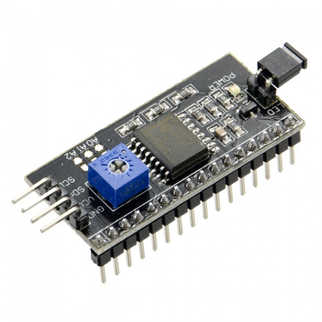 The fastest and most convenient way to use an i2c display in Arduino is to purchase a ready-made screen with built-in protocol support. But there are not very many of these screens and they are not cheap. But a huge number of different standard screens have already been produced. Therefore, the most affordable and popular option today is to purchase and use a separate I2C module - an adapter, which looks like this:
On one side of the module we see i2c pins - ground, power and 2 for data transfer. On the other adapter we see external power connectors. And, of course, the board has many pins with which the module is soldered to the standard screen pins.


i2c outputs are used to connect to the Arduino board. If necessary, we connect external power for backlighting. With the built-in trimmer we can set custom contrast values J
On the market you can find LCD 1602 modules with already soldered adapters; their use is simplified as much as possible. If you purchased a separate adapter, you will need to first solder it to the module.
Connecting the LCD screen to Arduino via I2C
To connect, you need the Arduino board itself, a display, a breadboard, connecting wires and a potentiometer.
If you are using a special separate i2c adapter, you must first solder it to the screen module. It's hard to make a mistake there, you can follow this scheme.

An LCD monitor with i2c support is connected to the board using four wires - two wires for data, two wires for power.
- The GND pin connects to GND on the board.
- The VCC pin is at 5V.
- SCL connects to pin A5.
- SDA is connected to pin A.


And it's all! No webs of wires, which are very easy to get tangled in. At the same time, we can simply entrust all the complexity of implementing the i2C protocol to libraries.
Libraries for working with i2c LCD display
To interact with Arduino and LCD 1602 via the I2C bus, you will need at least two libraries:
- The Wire.h library for working with I2C is already included in the standard Arduino program IDE.
- The LiquidCrystal_I2C.h library, which includes a wide variety of commands for controlling the monitor via the I2C bus and allows you to make the sketch simpler and shorter. You need to additionally install the library After connecting the display, you need to additionally install the LiquidCrystal_I2C.h library
After connecting all the necessary libraries to the sketch, we create an object and can use all its functions. For testing, let's load the following standard example sketch.
#include
Description of functions and methods of the LiquidCrystal_I2C library:
- home() and clear() - the first function allows you to return the cursor to the beginning of the screen, the second does the same, but at the same time deletes everything that was on the monitor before.
- write(ch) – allows you to print a single character ch to the screen.
- cursor() and noCursor() – shows/hides the cursor on the screen.
- blink() and noBlink() – the cursor blinks/does not blink (if its display was enabled before).
- display() and noDisplay() – allows you to connect/disable the display.
- scrollDisplayLeft() and scrollDisplayRight() – scrolls the screen one character left/right.
- autoscroll() and noAutoscroll() – allows you to enable/disable autoscroll mode. In this mode, each new character is written in the same place, displacing what was previously written on the screen.
- leftToRight() and rightToLeft() – Setting the direction of the displayed text – left to right or right to left.
- createChar(ch, bitmap) – creates a character with code ch (0 – 7), using an array of bitmap bitmaps to create black and white points.
Alternative library for working with i2c display
In some cases, errors may occur when using the specified library with devices equipped with PCF8574 controllers. In this case, the LiquidCrystal_PCF8574.h library can be suggested as an alternative. It extends LiquidCrystal_I2C, so there should be no problems using it.
Problems connecting i2c lcd display
If after uploading the sketch you do not see any message on the display, try the following steps.
First, you can increase or decrease the monitor's contrast. Often characters are simply not visible due to the contrast and backlight mode.
If this does not help, then check whether the contacts are connected correctly and whether the backlight power is connected. If you used a separate i2c adapter, then check again the quality of the soldering of the contacts.
Another common reason for missing text on the screen may be an incorrect i2c address. First try changing the device address in the sketch from 0x27 0x20 or to 0x3F. Different manufacturers may have different default addresses programmed. If this does not help, you can run the i2c scanner sketch, which scans all connected devices and determines their address using brute force. An example of an i2c scanner sketch.
If the screen still does not work, try unsoldering the adapter and connecting the LCD as usual.
Conclusion
In this article, we looked at the main issues of using an LCD screen in complex Arduino projects, when we need to save free pins on the board. A simple and inexpensive i2c adapter will allow you to connect a 1602 LCD screen, taking up only 2 analog pins. In many situations this can be very important. The price for convenience is the need to use an additional module - a converter and library. In our opinion, this is not a high price to pay for convenience and we highly recommend using this feature in projects.
What is an integral part of a large number of electronic devices? Of course, means of indication and graphical output of data. It is always more convenient and pleasant for the user when the result of the “smart box” can be seen visually. Therefore, today we will connect a display to the STM32 to display text and numbers. The hero of our experiments will be a rather popular display from Winstar. By the way, an important clarification appeared in the comments that the methodology is basically the same for all displays based on HD44780. Thanks to JekaKey for the important addition)
First, the display must be connected to the controller. Download the datasheet and look for the WH1602 pinout. Look here:
As you know, display WH1602 has 16 pins. Let's look at each one separately...
Pins Vss, Vdd and K need to be connected to ground and to power, that is, exactly as indicated in the table, there are no surprises and nothing even to discuss)
Pin number 3 is used to adjust the contrast - if we apply +5V there, we will see absolutely nothing, and if we short-circuit the pin to ground, we will admire two rows of black squares 😉 Naturally, this does not suit us, so we need to hang a potentiometer (resistor) there with variable resistance) to adjust the contrast. The best visibility of characters is provided by a voltage of 0.5-0.7 V at this display pin.
The RS pin is already a pin that we ourselves will control using a microcontroller. A low voltage level (0) on this pin means that a command will now follow, a high level (1) means that there will now be data to be written to the display memory.
Pin R/W - it’s clear here, either we read the data (display busy flag, for example), in this case there is 1 on this pin, or we write the command/data to the display, then we have 0 here.
DB7 – DB0 – data bus, and that says it all)
Pin E is the so-called Enable signal. This is what he is needed for. To work with the display - record data or issue a command - we need to issue a positive pulse to this pin. That is, the procedure will look like this:
- On pins RS, R/W, DB7 - DB0 - the necessary signals corresponding to our command.
- We supply one to pin E.
- Zhdems (according to the datasheet – at least 150 ns)
- We apply a low level (0) to pin E.
You need to put 4.2 V on the A/Vee leg to power the display backlight.
This is how communication with the WH1602 display occurs.
We’ve figured out connecting the WH1602, but before moving on to the example, let’s look at what commands our display generally understands. To do this, we go into the datasheet and find an interesting table:

All commands and signals that should be on the corresponding pins of the WH1602 for each specific command are described here. For example, we want to clear the display, we look at the table, and here is the command we need! Clear Display!
We apply zeros to pins RS, R/W, DB7, DB6, DB5, DB4, DB3, DB2, DB1, and one to pin DB0. Done! What's next? That's right, one on pin E, then wait a while and lower E to zero again. That's it, the display is cleared 😉 Just before executing the next command you must pause, indicated in the datasheet for each command. It would be more effective to poll the busy flag; as soon as it is reset to 0, you can continue working. There is also a special command for reading this flag, so everything is clear with this) Let's move on...
And, in fact, everything is with the theory, you can already try to write something. To make working with the display easier, I made a small library, now let's see how it can be used. First, download
We get 2 files at our disposal, MT_WH1602.c and MT_WH1602.h. We tear off the second one, here we need to select the pins and the controller used.
By the way, my display is connected like this:
RS-PC2
R/W – PB10
E–PB14
DB7–PD2
DB6–PC12
DB5–PA8
DB4–PA10
DB3–PA15
DB2–PD11
DB1–PA3
DB0–PA5
Open the file MT_WH1602.h:
| #define PLATFORM (STM32F10x) |
Next, select the microcontroller pins to which the display is connected. Just first let’s set which ports we use. When I connect, I use GPIOA, GPIOB, GPIOC and GPIOD, we write:
Similarly for other microcontroller legs.
We're done with the setup, let's continue) To call the commands given at the beginning of the article, the MT_WH1602.c file contains the following functions (they are named after the names of the commands, so I think everything is clear):
| void MT_WH1602_ClearDisplay(void ) ; void MT_WH1602_ReturnHome(void ) ; void MT_WH1602_EntryModeSet (bool IDaddress, bool shift) ; void MT_WH1602_DisplayOnOff (bool Dbit, bool Cbit, bool Bbit) ; void MT_WH1602_CursorOrDisplayShift (bool SCbit, bool RLbit) ; void MT_WH1602_FunctionSet (bool DLbit, bool Nbit, bool Fbit) ; void MT_WH1602_SetCGRAMAddress (uint8_t address) ; void MT_WH1602_SetDDRAMAddress (uint8_t address) ; bool MT_WH1602_ReadBusy(void ) ; void MT_WH1602_WriteData(uint8_t data) ; |
For some commands we need to pass parameters to the function, for example:
| void MT_WH1602_DisplayOnOff (bool Dbit, bool Cbit, bool Bbit) ; |
Let's look at the command table:
We see that the Display ON/OFF command not only turns on/off the display, but also activates/deactivates the cursor and cursor blinking. In the datasheet, these command bits are designated as D, C and B, and we pass them as parameters to the function. If we need to turn on the display and cursor, but disable cursor blinking, we call the command as follows:
MT_WH1602_DisplayOnOff(1, 1, 0);
In general, everything is simple 😉
In short, we create new project, add a library for working with the WH1602 display, create an empty .c file and start filling it with code:
| // Include the library file#include "MT_WH1602.h" /*******************************************************************/ int main(void) ( // Call the initialization function, we can’t do without it =)() ; // Now we need to make the initial display configuration // Documentation and the Internet recommend doing this ;) MT_WH1602_FunctionSet(1, 0, 0); MT_WH1602_Delay(1000 ) ; MT_WH1602_FunctionSet(1, 0, 0); MT_WH1602_Delay(1000 ) ; MT_WH1602_FunctionSet(1, 0, 0); MT_WH1602_Delay(1000 ) ; MT_WH1602_FunctionSet(1, 1, 1); MT_WH1602_Delay(1000 ) ; MT_WH1602_DisplayOnOff(1, 0, 0); MT_WH1602_Delay(1000 ) ; MT_WH1602_ClearDisplay() ; MT_WH1602_Delay(2000) ; // For example, I took the first delay values that came to mind) // In general, you need to check the display busy flag // Let's now display something, like the name of our site MT_WH1602_WriteData(0x6D) ; MT_WH1602_Delay(100) ; MT_WH1602_WriteData(0x69) ; MT_WH1602_Delay(100) ; MT_WH1602_WriteData(0x63) ; MT_WH1602_Delay(100) ; MT_WH1602_WriteData(0x72) ; MT_WH1602_Delay(100) ; MT_WH1602_WriteData(0x6F) ; MT_WH1602_Delay(100) ; MT_WH1602_WriteData(0x74) ; MT_WH1602_Delay(100) ; MT_WH1602_WriteData(0x65) ; MT_WH1602_Delay(100) ; MT_WH1602_WriteData(0x63) ; MT_WH1602_Delay(100) ; MT_WH1602_WriteData(0x68) ; MT_WH1602_Delay(100) ; MT_WH1602_WriteData(0x6E) ; MT_WH1602_Delay(100) ; MT_WH1602_WriteData(0x69) ; MT_WH1602_Delay(100) ; MT_WH1602_WriteData(0x63) ; MT_WH1602_Delay(100) ; MT_WH1602_WriteData(0x73) ; MT_WH1602_Delay(100) ; MT_WH1602_WriteData(0x2E) ; MT_WH1602_Delay(100) ; MT_WH1602_WriteData(0x72) ; MT_WH1602_Delay(100) ; MT_WH1602_WriteData(0x75) ; MT_WH1602_Delay(100) ; while (1 ) ( __NOP() ; ) ) /*******************************************************************/ |
Done, let's check) 
As you can see, everything works correctly)
By the way, I somehow lost sight of the question of what to write on the display in order to display this or that character. Here is the plate from the datasheet: 
So, in order to determine what value to write into the display memory, you need to take the numbers written at the top and left in this table for a specific symbol. For example, the symbol “A”. Let's see - this symbol corresponds to column 0100 (0x4) and line 0001 (0x1). It turns out that to display the symbol “A” you need to write the value 0x41 into the display.
That's it now =) We've sorted out the connection and operation of the WH1602 display, so see you soon!
P.S. When working with the library, I did not test the function of reading the busy flag, so if suddenly something does not work as it should, write, we will figure it out)
Sometimes we are faced with the problem of outputting various information from Arduino to the outside world. Often, using a serial port is impossible, inconvenient and unprofitable.
A character display is one of the simplest and cheapest means of displaying information because it has its own microcontroller that stores the encoded characters. This system simplifies the use of these displays, but at the same time limits their use to output only text information, unlike graphic displays.
In the example, we will look at the Winstar wh1602l1 display, one of the most common displays on the hd44780 controller. In addition, you can connect LCD 2004 and other similar ones.
The first two digits indicate the number of characters per line, and the second the number of lines, so the selected display has 2 lines of 16 characters.
This connection method involves occupying at least 6 ports of the Arduino microcontroller. If necessary, you can connect the 1602 text display via the I2C interface (2 ports).
Of the additional elements we need variable resistor, to control contrast. Otherwise, everything is connected according to the diagram, according to the datasheet and the selected Arduino outputs in the program.
Pins 15 and 16 on the display are responsible for the backlight; it can be turned off or the brightness can be automatically adjusted when connecting a photoresistor to the Arduino as a brightness sensor.
In our example, we will read data from the serial port and display it on the display:
#include
You can complicate the code and output the DS1307 real time clock on Arduino to your LCD1602.
Now let's take a closer look at all the functions in the library LiquidCrystal:
The first and most important thing is that using this library you cannot display Russian letters, even if the display has these characters in memory. This problem can be solved either by other libraries, or by writing values using hexadecimal code.
lcd.print();- the simplest and most frequently used, used to display information.
lcd. clear(); - used to clean the display.
lcd.setCursor(x, y); - places the cursor at a specific place.
X – change of position in the line
Y – line change
For example, lcd.setCursor(0, 0); this is the top left cell.
lcd.home(); - places the cursor at position 0, 0
lcd.home(); = lcd.setCursor(0, 0);
lcd. scrollDisplayLeft(); - shift left
lcd. scrollDisplayRight(); - shift right
Lcd.createChar(Name, array); - creating your own sign.
For example, the degree sign looks like this:
Celc = (B00111, B00101, B00111, B00000, B00000, B00000, B00000, B00000 );


