USB programmer for pic family chips. How to program PIC microcontrollers or Simple JDM programmer. Features of practical use
USB PIC controller programmer - 3.8 out of 5 based on 11 votes
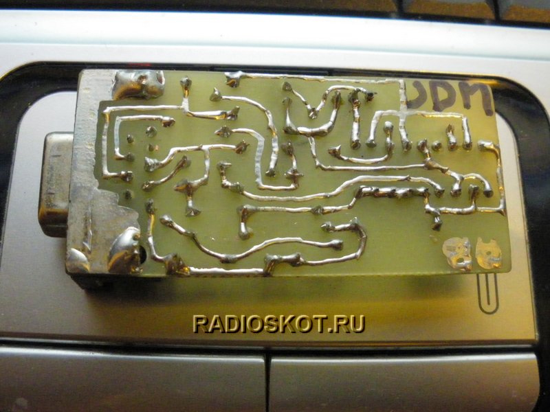
Photos of the programmer provided by Ansagan Khasenov
This article discusses the practical aspects of assembling a simple USB programmer for PIC microcontrollers, which has the original name GTP-USB (Grabador TodoPic-USB). There is an older model of this GTP-USB plus programmer that also supports AVR microcontrollers, but is offered for money. Unambiguous information on the circuits and firmware for GTP-USB plus could not be found. If you have information on GTP-USB plus, please contact me.
So, GTP-USB. This programmer is assembled on a PIC18F2550 microcontroller. GTP-USB cannot be recommended for beginners, because... assembly requires flashing the PIC18F2550 and requires a programmer for this. A vicious circle, but not so vicious that it becomes an obstacle to assembly.
From original scheme GTP-USB display elements are excluded to simplify the printed circuit board design. The main indicator is the monitor of your computer, on which you can monitor the programming process from the WinPic800 version 3.55G or 3.55B program.
Lightweight GTP-USB circuit.
Signal lines Vpp1 and Vpp2 are defined for microcontrollers in packages with different numbers of pins. The Vpp/ICSP line is defined for in-circuit programming. The rest of the lines are standard.
The programmer is assembled on a single-sided printed circuit board.
The adapter can be painlessly connected to any other PIC microcontroller programmer, which is certainly convenient.
After assembly, we turn it on for the first time. When GTP-USB is connected to the PC for the first time, a message appears

This is followed by the traditional driver installation prompt. The driver is located in the WinPic800 control program at the approximate path \WinPic800 3.55G\GTP-USB\Driver GTP-USB\.

We agree with the warnings and continue the installation.
Paying attention. This programmer circuit and its firmware have been tested in practice and work with the WinPic800 control program versions 3.55G and 3.55B. Older versions, for example 3.63C, do not work with this programmer. Making the settings control program: in the Settings - Hardware menu, select GTP-USB-#0 or GTP-USB-#F1 and click Apply.
Click on the button on the panel and test the equipment. As a result of successful testing, a message appears (see below), which makes us happy.

This programmer worked perfectly with the following controllers (from what was available): PIC12F675, PIC16F84A, PIC16F628A, PIC16F874A, PIC16F876A, PIC18F252. Test of controllers, writing and reading data - completed successfully. The speed of work is impressive. Reading 1-2 sec. Recording 3-5 sec. No glitches were noticed. Some of the hardwired MKs have been tested in hardware - they work.


Represents the most simple design for flashing PIC family controllers. Undeniable advantages - simplicity, compactness, power supply without external source This classic programmer circuit has made it very popular among radio amateurs, especially since the circuit is already 5 years old, and during this time it has established itself as a simple and reliable tool for working with microcontrollers.
Schematic diagram of the programmer for pic controllers:

No power is required for the circuit itself, because this is done by the COM port of the computer, through which the microcontroller firmware is controlled. For low-voltage programming mode, 5V is sufficient, but all options for change (fuses) may not be available. The COM-9 port connection connector was mounted directly on the PIC programmer circuit board - it turned out very convenient.
You can plug the board directly into the port without any extra cords. tested on various computers and when programming MK series 12F, 16F and 18F, showed high quality firmware. The proposed circuit allows programming PIC12F509, PIC16F84A, PIC16F628 microcontrollers. For example, recently, using the proposed programmer, a microcontroller for .
For programming, WinPic800 is used - one of best programs for programming PIC controllers. The program allows you to perform operations for microcontrollers of the PIC family: reading, writing, erasing, checking FLASH and EEPROM memory and setting configuration bits.
It just so happened that I began my acquaintance with microcontrollers with AVR. For the time being, I avoided PIC microcontrollers. But, nevertheless, they also have unique designs that are interesting to repeat! But these microcontrollers also need to be flashed. I am writing this article mainly for myself. In order not to forget technology, how to flash a PIC microcontroller without problems and waste of time.
How to program PIC microcontrollers or Simple JDM programmer
For the first circuit - I tried long and hard to make a PIC programmer using circuits found on the Internet - nothing came of it. It's a shame, but I had to turn to a friend to flash the MK. But it’s not a good idea to constantly run around with friends! This same friend recommended a simple circuit that works from a COM port. But even when I assembled it, nothing worked. After all, it’s not enough to assemble the programmer - you also need to customize the program for it, which we will use to flash it. But that’s exactly what I couldn’t do. There are a whole bunch of instructions on the Internet, and few of them helped me...
Then, I managed to flash one microcontroller. But since I was doing the stitching under severe time pressure, I didn’t think to save at least a link to the instructions. And I didn’t find her afterwards. Therefore, I repeat - I am writing an article to have my own instructions.
So, a programmer for PIC microcontrollers. Simple, although not 5 wires, as for AVR microcontrollers, which I still use today. Here's the diagram: 
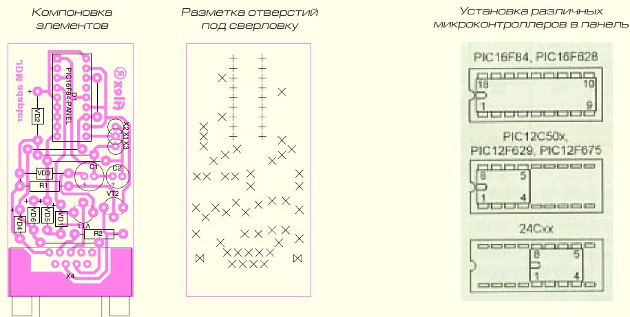
Here is the printed circuit board (). 
The COM connector is soldered with pins directly onto the contact pads (the main thing is not to get confused with the numbering). The second row of pins is connected to the board with small jumpers (I said it very unclearly, yeah). I’ll try to give you a photo... even though it’s scary (I don’t have a normal camera right now).  The worst thing is that PIC microcontrollers require 12 volts for firmware. And it’s better not 12, but a little more. Let's say 13. Or 13.5 (by the way, experts - correct me in the comments if I'm wrong. Please.). 12 volts can still be obtained somewhere. Where is 13? I simply got out of the situation - I took a freshly charged lithium-polymer battery, which had 12.6 volts. Well, or even a four-cell battery, with its 16 volts (I flashed one PIC like this - no problem).
But I got distracted again. So - instructions for flashing PIC microcontrollers. We are looking for the WinPIC800 program (unfortunately, the simple and popular icprog did not work for me) and setting it up as shown in the screenshot.
 After that, open the firmware file, connect the microcontroller and flash it.
Circuits using microcontrollers are gaining quite a lot of popularity on the Internet. A microcontroller is a special chip that, in essence, is a small computer with its own input/output ports and memory. Thanks to the microcontroller, you can create very functional circuits with a minimum of passive components, for example, Digital Watch, players, various LED effects, automation devices.
In order for the microcircuit to begin performing any functions, it needs to be flashed, i.e. load the firmware code into its memory. This can be done using a special device called a programmer. The programmer connects the computer on which the firmware file is located with the microcontroller being flashed. It is worth mentioning that there are microcontrollers of the AVR family, for example, Atmega8, Attiny13, and pic series, for example PIC12F675, PIC16F676. The Pic series belongs to Microchip, and the AVR series belongs to Atmel, so the firmware methods for PIC and AVR are different. In this article we will look at the process of creating an Extra-pic programmer, with which you can flash a pic series microcontroller.
The advantages of this particular programmer include the simplicity of its circuitry, reliability of operation, and versatility, because it supports all common microcontrollers. The computer is also supported by the most common firmware programs, such as Ic-prog, WinPic800, PonyProg, PICPgm.
Programmer circuit

It contains two microcircuits, the imported MAX232 and the domestic KR1533LA3, which can be replaced with the KR155LA3. Two transistors, KT502, which can be replaced with KT345, KT3107 or any other low-power PNP transistor. KT3102 can also be changed, for example, to BC457, KT315. The green LED serves as an indicator of power availability, the red LED lights up during the microcontroller firmware process. The 1N4007 diode is used to protect the circuit from the supply of voltage of incorrect polarity.
Materials

List of parts required to assemble the programmer:
- Stabilizer 78L05 – 2 pcs.
- Stabilizer 78L12 – 1 pc.
- LED 3 V. green – 1 pc.
- LED 3 V. red – 1 pc.
- Diode 1N4007 – 1 pc.
- Diode 1N4148 – 2 pcs.
- Resistor 0.125 W 4.7 kOhm – 2 pcs.
- Resistor 0.125 W 1 kOhm – 6 pcs.
- Capacitor 10 uF 16V – 4 pcs.
- Capacitor 220 uF 25V – 1 pc.
- Capacitor 100 nF – 3 pcs.
- Transistor KT3102 – 1 pc.
- Transistor KT502 – 1 pc.
- Chip MAX232 – 1 pc.
- Chip KR1533LA3 – 1 pc.
- Power connector – 1 pc.
- Connector COM port“mother” - 1 pc.
- DIP40 socket – 1 pc.
- DIP8 socket – 2 pcs.
- DIP14 socket – 1 pc.
- DIP16 socket – 1 pc.
- DIP18 socket – 1 pc.
- DIP28 socket – 1 pc.
PCB manufacturing
The programmer is assembled on a printed circuit board measuring 100x70 mm. The printed circuit board is made using the LUT method, the file is attached to the article. There is no need to mirror the image before printing.
Download the board:
(downloads: 639)
Programmer assembly
First of all, jumpers are soldered onto the printed circuit board, then resistors, diodes. Lastly, you need to solder the sockets and power connectors and COM port.

Because on printed circuit board There are a lot of sockets for flashable microcontrollers, but not all of their pins are used, you can use this trick and remove the unused contacts from the sockets. At the same time, less time will be spent on soldering and inserting a microcircuit into such a socket will be much easier.

The COM port connector (called DB-9) has two pins that must be “stuck” into the board. In order not to drill extra holes on the board for them, you can unscrew the two screws under the sides of the connector, and the pins will fall off, as will the metal edging of the connector.

After soldering all the parts, the board must be washed from flux, and the adjacent contacts must be ringed to see if there are any short circuits. Make sure that there are no microcircuits in the sockets (you need to remove both MAX232 and KR1533LA3), connect the power. Check if there is a voltage of 5 volts at the outputs of the stabilizers. If everything is fine, you can install the MAX232 and KR1533LA3 microcircuits, the programmer is ready for use. The supply voltage of the circuit is 15-24 volts.

The programmer board contains 4 sockets for microcontrollers and one for flashing memory chips. Before installing the microcontroller to be flashed on the board, you need to check whether its pinout matches the pinout on the programmer board. The programmer can be connected to the computer's COM port directly or via an extension cable. Happy build!

Quickly assembling a circuit you like on a microcontroller is not a problem for many radio amateurs. But many people starting to work with microcontrollers are faced with the question of how to program it. One of the simplest programmer options is the JDM programmer.
Programmer ProgCode v 1.0 This program works in WindowsXP. Allows programming PIC controllers of the middle family (PIC16Fxxx) via the COM port of the computer. The programmer connection indicator (in the upper right corner of the window) turns red if there is no programmer on the port selected in the settings. If the programmer is connected, the program detects it and the indicator in the upper right corner takes the form shown in Figure 1. The control panel is located on the left side of the program window. This panel can be minimized by clicking on the button in the toolbar or by clicking on the left edge of the window (this is convenient when the program window is maximized to full screen).
Figure (screenshot of the ProgCode v1.0 program)
If a HEX file is loaded into the program, then it is advisable to first select in the list of controllers the MK for which the loaded firmware is designed. If this is not done, then the file designed for a microcontroller with a memory larger than that selected in the list will be cut off and parts of the program will be lost - with this option for loading the file, a warning is displayed.

If this does not happen, then you can select the desired controller after loading the file into the program.
SFR file formatProgCode programmer supports working with its own file format. These files have the extension .SFR and allow you to store Additional information about a program designed for a microcontroller. This file stores information about the type of microcontroller. This allows you to not worry about pre-selecting the MK type in the settings when loading an SFR file.
Port and protocol settings when connecting the programmer After installing the program, by default all the settings that are necessary for the programmer to work with the JDM circuit given on this page are set.
Signal inversion in the above circuit is needed only for the OutData output, since in this circuit the signal is inverted by the matching transistor. On all other pins, inversion is disabled.

The pulse delay can be equal to 0. Its adjustment is provided for “particularly difficult” controller instances that cannot be flashed. The same applies to the recording pause allowance - it is zero by default. If you increase these settings, the controller programming time will increase significantly.
The “check on write” checkbox should be checked if you need to “on the fly” check everything that is written to the microcontroller for correctness and compliance with the source file. If you uncheck this box, the check will not be performed at all and there will be no error messages, even if such errors actually exist.
Select port speed - the speed can be any. For a JDM programmer this parameter has no meaning.
Windows XP uses buffering of data sent over COM ports information. These are so-called FIFO buffers. To avoid errors when programming via JDM, this mechanism must be disabled. You can do this in Windows Device Manager.
Go to the control panel, then:
Administration - Computer Management - Device Manager
Then select the port to which the JDM programmer is connected (for example COM1) - look at the properties - port parameters tab - additional. And uncheck the box "Use FIFO buffers"
Figure - Setting up a COM port to work with a JDM programmer

After this, restart the computer.
Browser for local projects In addition to directly programming controllers, the program implements a convenient browser for projects on the MK, located both on local folders on the computer and on the Internet. This was done for ease of use. Often the necessary projects are located in different folders, and you have to spend time getting to the right directory in order to view the project. Here you can easily add the necessary folders to the list of folders and view any project with two or three mouse clicks.
When you double-click on it in the browser panel, any file will open in the program itself - this applies to pictures, html files, doc, rtf, djvu (if installed plugins), pdf, txt, asm. The file can also be opened by double-clicking in a browser using an external program installed on the computer. To do this, the extension of the desired file type must be entered in the "File Associations" list. If you do not specify the path to the opening program, Windows will open the file in the program by default (this is convenient for opening archives that are not always clearly opened). If the path to the opening program is specified in the list, the file will open in the specified program. It is convenient to view files like SPL, LAY, DSN in this way.
Figure (screenshot of the ProgCode v1.0 program browser)

This is what the file association settings window looks like:

Project Browser on the Internet Project Browser on the Internet, just like the local project browser, allows you to quickly go to the desired site on the Internet with a couple of clicks, view the project and, if necessary, immediately flash the program in MK.

When reviewing projects on the Internet, if on the project page there is a link to a file with the SFR extension (this is the file format of the ProgCode program), then when you click on it, such a file will open in a new program tab and is immediately ready for flashing into the microcontroller.
The list of links can be edited using the "Edit" button. This will open a window for editing the list of links:

Description of the chip programming process Most modern chips contain flash memory, which is programmed using the I2C protocol or similar protocols.
Rewritable memory is found in PIC, AVR and other controllers, memory chips such as 24Cxx, and similar ones, various memory cards such as MMC and SD, ordinary USB flash cards that connect to the computer via a USB connector. Let's consider writing information into the flash memory of the PIC16F628A microcontroller. There are 2 lines DATA and CLOCK through which information is transmitted. The CLOCK line is used to supply clock pulses, and the DATA line is used to transmit information.
To transfer 1 bit of information to the microcontroller, you need to set 0 or 1 (depending on the value of the bit) on the data line (DATA) and create a voltage drop (transition from 1 to 0) on the clock line (CLOCK).
One bit for a controller is not enough. He waits for five more in order to perceive this 6-bit message as a command. The controller really likes commands, and they must consist of 6 bits - such is the nature of the PIC16.
Here is the list and meaning of commands that PIC is able to understand. There are not so many commands - the vocabulary of this controller is small, but don’t think that it is completely stupid - there are devices with fewer commands "LoadConfiguration" 000000 - Loading configuration
"LoadDataForProgramMemory" 000010 - Loading data into program memory
"LoadDataForDataMemory" - 000011 - Loading data into data memory (EEPROM)
"IncrementAddress" 000110 - Increase the address of the PC MK
"ReadDataFromProgramMemory" 000100 - Reading data from program memory
"ReadDataFromDataMemory" 000101 - Reading data from data memory (EEPROM)
"BeginProgrammingOnlyCycle" 011000 - Start programming cycle
"BulkEraseProgramMemory" 001001 - Complete erase of program memory
"BulkEraseDataMemory" 001011 - Complete erase of data memory (EEPROM)
"BeginEraseProgrammingCycle" 001000 - Begin a programming cycle. The controller responds to these commands differently. In different ways, after issuing the command, you need to continue the conversation with him.
In order to begin a full-fledged programming process, you must also apply a voltage of 12 volts to the MCLR pin of the controller, and then apply a supply voltage to it. It is in this sequence of voltage supply that there is a certain meaning. After power is applied, if the PIC is configured to run from the internal RC oscillator, it may begin executing its own program, which is not allowed when programming, as failure is inevitable.
Preliminary supply of 12 volts to the MCLR allows you to avoid such a development.
When writing information to the flash memory of MK programs after the command "LoadDataForProgramMemory" 000010 - Loading data into program memory, the data itself must be sent to the controller - 16 bits,
which look like this: “0xxxxxxxxxxxxxx0”. The crosses in this word are the data itself, and the zeros at the edges are sent as a frame - this is the standard for PIC16. There are only 14 significant bits in a word. This series of controllers has a 14-bit command representation format.
After the data word transmission has finished, the PIC waits for the next command.
Since our goal is to write a word into the program memory of the MK, the next command should be the command
"BeginEraseProgrammingCycle" 001000 - Begin the programming cycleHaving received it, the controller is disconnected from the outside world for 6 milliseconds, which it needs to complete the writing process. The signals at the microcontroller pins are generated by the computer using special programs- programmers. COM, LPT or USB ports can be used for signal transmission. Programs such as PonyProg, IsProg, WinPic800 work with the JDM programmer.
JDM programmer circuit simple circuit programmer is shown in the figure. Although this circuit does not implement control of the voltage supply sequence, it is very simple and it is possible to assemble such a circuit very quickly, using a minimum of parts.
Figure (JDM programmer circuit)

One of the questions when connecting a programmer to a computer is how to ensure selective isolation. To avoid damage to the COM port in the event of a malfunction in the circuit. Some designs use the MAX232 IC, which provides selective isolation and signal level matching. In this scheme, the issue is solved more simply - by using battery power. The signal level coming from the computer is limited by zener diodes VD1, VD2, and VD3. Despite the simplicity of the JDM programmer circuit, it can be used to program most types of PIC microcontrollers. The jumper between pins COM6 (DSR) and COM7 (RTS) is designed so that the program can determine that the programmer is connected to the computer.
The connection of the programmer outputs to a specific MK depends on the type of MK. Often, several panels are mounted on the programmer board, which are designed for a specific type of controller.
The table shows the purpose of the legs of some types of MK during programming.

Figures are shown with the assignment of the pins of the most common microcontrollers during programming. Pinout (pinout) of microcontrollers PIC16F876A, PIC16F873A in a DIP28 package.
 Pinout of microcontrollers PIC16F874A, PIC16F877A in DIP40 housing.
  Pinout (pinout) of microcontrollers PIC16F627A, PIC16F628A, PIC16F648A in DIP18 housing.
 The PIC16F84 and PIC16F84A MCUs have the same arrangement of pins intended for programming.

The assignment of pins for microcontrollers of the PIC16Fxxx series, depending on the type of case, is in most cases standard, but if there is any doubt about this, then it is most reliable to check the datasheet for a specific instance of the MK. Some of the documentation is available on the Russian website http://microchip.ru A complete collection of datasheets and other documentation is on the website of the PIC microcontroller manufacturer: http://microchip.com
Project Index The program allows you to directly go to the index page, view the description of the desired project in a couple of clicks, and immediately flash the program into the controller.

If you need to flash the controller with the selected firmware, click on the SFR file, for example Timer_a.sfr
The program downloads the file from the server to a new tab.

After this, all that remains is to insert the MK into the programmer socket, if this has not already been done, and click on the “Write all” button.
The program is recorded in MK. After this, the controller is inserted into the device board and the device is ready for operation.
You can download the program on the file download page: http://cxema.my1.ru/load/proshivki/material_k_state_prostoj_jdm_programmator_dlja_pic_mikrokontrollerov/9-1-0-1613 Section:


