Kharchenko antenna parameters. Antenna for receiving terrestrial television in DVB-T2 format. Use of aluminum racks
Do you want to collect a long-range WiFi antenna, then you should know about some of its features.
The first and simplest: large antennas of 15 or 20 dBi (isotropic decibels) are the maximum power, and there is no need to make them even more powerful.
Here is a clear illustration of how, as the antenna power in dBi increases, its coverage area decreases.
It turns out that as the antenna’s operating distance increases, its coverage area decreases significantly. At home, you will have to constantly catch a narrow band of signal coverage if the WiFi emitter is too powerful. Get up from the couch or lie down on the floor, and the connection will immediately disappear.
That's why home routers have conventional 2 dBi antennas that radiate in all directions - so they are most effective over short distances.
Directed
9 dBi antennas only work in a given direction (directional) - they are useless in a room, they are better used for long-distance communications, in the yard, in the garage next to the house. The directional antenna will need to be adjusted during installation to transmit a clear signal in the desired direction.
Now to the question of carrier frequency. Which antenna will work better at long range, 2.4 or 5 GHz?
Now there are new routers operating at double the frequency of 5 GHz. These routers are still new and are good for high-speed data transfer. But the 5 GHz signal is not very good for long distances, as it fades faster than 2.4 GHz.
Therefore, old 2.4 GHz routers will work better in long-range mode than new high-speed 5 GHz ones.
Drawing of a double homemade biquadrat
The first examples of homemade WiFi signal distributors appeared back in 2005.
The best of them are the biquadrate designs, which provide a gain of up to 11–12 dBi, and the double biquadrate, which has a slightly better result of 14 dBi.
According to usage experience, the biquadrate design is more suitable as a multifunctional emitter. Indeed, the advantage of this antenna is that with the inevitable compression of the radiation field, the signal opening angle remains wide enough to cover the entire area of the apartment when installed correctly.
All possible versions of a biquad antenna are easy to implement. 
Required Parts
- Metal reflector - a piece of foil-textolite 123x123 mm, a sheet of foil, a CD, a DVD CD, an aluminum lid from a tea can.
- Copper wire with a cross section of 2.5 mm2.
- A piece of coaxial cable, preferably with a characteristic impedance of 50 Ohms.
- Plastic tubes - can be cut from a ballpoint pen, felt-tip pen, marker.
- A little hot glue.
- N-type connector - useful for conveniently connecting an antenna.
For the 2.4 GHz frequency at which the transmitter is planned to be used, the ideal biquadrate size would be 30.5 mm. But still we don't satellite dish, therefore, some deviations in the dimensions of the active element are allowed - 30–31 mm.
The issue of wire thickness also needs to be considered carefully. Taking into account the selected frequency of 2.4 GHz, a copper core must be found with a thickness of exactly 1.8 mm (section 2.5 mm2).
From the edge of the wire we measure a distance of 29 mm to the bend.
We make the next bend, checking the outer size of 30–31 mm.
We make the next inward bends at a distance of 29 mm.
We check the most important parameter of the finished biquadrat -31 mm along the center line.
We solder the places for future fastening of the coaxial cable leads.
Reflector
The main task of the iron screen behind the emitter is to reflect electromagnetic waves. Correctly reflected waves will superimpose their amplitudes on the vibrations just released by the active element. The resulting amplifying interference will make it possible to propagate electromagnetic waves as far as possible from the antenna.
To achieve useful interference, the emitter must be positioned at a distance that is a multiple of a quarter of the wavelength from the reflector.
Distance from emitter to reflector for biquad and double biquad antennas we find lambda / 10 - determined by the features of this design / 4.
Lambda is a wavelength equal to the speed of light in m/s divided by the frequency in Hz.
Wavelength at a frequency of 2.4 GHz is 0.125 m.
Increasing the calculated value five times, we get optimal distance - 15.625 mm.
Reflector size affects the antenna gain in dBi. The optimal screen size for a biquad is 123x123 mm or more, only in this case can a gain of 12 dBi be achieved.
The sizes of CDs and DVDs are clearly not enough for complete reflection, so biquad antennas built on them have a gain of only 8 dBi.
Below is an example of using a tea jar lid as a reflector. The size of such a screen is also not enough, the antenna gain is less than expected.
Reflector shape should only be flat. Also try to find plates that are as smooth as possible. Bends and scratches on the screen lead to the dispersion of high-frequency waves due to disruption of reflection in a given direction.
In the example discussed above, the sides on the lid are clearly unnecessary - they reduce the signal opening angle and create scattered interference.
Once the reflector plate is ready, you have two ways to assemble the emitter on it.
- Install the copper tube using soldering.
To fix the double biquadrat, it was necessary to additionally make two stands from a ballpoint pen.
- Secure everything to the plastic tube using hot glue.
We take a plastic box for discs for 25 pieces.
Cut off the central pin, leaving a height of 18 mm.
Use a file or file to cut four slots in the plastic pin.
We align the slots to the same depth
We install the homemade frame on the spindle, check that its edges are at the same height from the bottom of the box - about 16 mm.
Solder the cable leads to the emitter frame.
Taking a glue gun, we attach the CD to the bottom of the plastic box.
We continue to work with a glue gun and fix the emitter frame on the spindle.
WITH reverse side We fix the cable boxes with hot glue.
Connecting to a router
Those who have experience can easily solder to the contact pads on the circuit board inside the router.
Otherwise, be careful, thin traces may come off the printed circuit board when heated for a long time with a soldering iron.
You can connect to an already soldered piece of cable from a native antenna via an SMA connector. You shouldn't have any problems purchasing any other N-type RF connector from your local electronics store.
Antenna tests
Tests have shown that an ideal biquad gives a gain of about 11–12 dBi, and this is up to 4 km of directional signal.
The CD antenna gives 8 dBi, since it can pick up a WiFi signal at a distance of 2 km.
Double biquadrate provides 14 dBi - slightly more than 6 km.
The opening angle of antennas with a square emitter is about 60 degrees, which is quite enough for the yard of a private house.
About the range of Wi-Fi antennas
From a native router antenna of 2 dBi, a 2.4 GHz signal of the 802.11n standard can spread over 400 meters within line of sight. Signals of 2.4 GHz, old standards 802.11b, 802.11g, travel worse, having half the range compared to 802.11n.
Considering a WiFi antenna to be an isotropic emitter - an ideal source that distributes electromagnetic energy evenly in all directions, you can be guided by the logarithmic formula for converting dBi to power gain.
Isotropic decibel (dBi) is the antenna gain, determined as the ratio of the amplified electromagnetic signal to its original value multiplied by ten.
AdBi = 10lg(A1/A0)
Conversion of dBi antennas into power gain.
| A,dBi | 30 | 20 | 18 | 16 | 15 | 14 | 13 | 12 | 10 | 9 | 6 | 5 | 3 | 2 | 1 |
| A1/A0 | 1000 | 100 | ≈64 | ≈40 | ≈32 | ≈25 | ≈20 | ≈16 | 10 | ≈8 | ≈4 | ≈3.2 | ≈2 | ≈1.6 | ≈1.26 |
Judging by the table, it is easy to conclude that a directional WiFi transmitter with a maximum permissible power of 20 dBi can distribute a signal over a distance of 25 km in the absence of obstacles.
The directional "double square" antenna was first described in the literature in 1948 and has since continued to attract attention from radio amateurs.
The “double square” antenna (Fig. 2-56), which has optimal dimensions, provides a gain relative to a conventional vibrator of 8 dB, which corresponds to the gain provided by a three-element “wave channel” antenna. From a practical point of view, the “double square” antenna is even superior to the three-element “wave channel” antenna, since it has greater directivity in the vertical plane and a flat angle of vertical radiation, which is especially important when establishing long-distance communications. A "double square" antenna is usually made from thin copper wire, or better yet, antenna cord, and does not require expensive metal tubular structures. Manufacturing the supporting structure of the antenna is somewhat more complicated.
In Fig. Figure 2-56 shows a diagram of a double square antenna in two forms in which it is usually implemented. The main element is a vibrator in the form of a wire square with a side length of λ/4 and a total length of 1λ. At a distance A from 0.1λ to 0.2λ, a second similar square is placed, equipped with an additional quarter-wave loop, thanks to which this antenna element acts as a reflector. The antenna elements are located either vertically (Fig. 2-56, a), or on one of the sides of the square (Fig. 2-56, b). Without changing the antenna design, moving the feed point, you can achieve vertical or horizontal polarization of the field. Both antennas (Fig. 2-56) have horizontal field polarization.
The “double square” antenna radiates in one direction, i.e. the return radiation is greatly attenuated. The direction of the main radiation is perpendicular to the antenna plane and directed away from the reflector to the vibrator. The maximum gain of the antenna, as many authors indicate, when the reflector is located at a distance of 0.2λ from the vibrator lies in the range from 10 to 11 dB (measurements carried out by radio amateur G 4ZU, with the indicated dimensions gave a gain value of 8 dB).
The input impedance of the vibrator itself ranges from 110 to 120 ohms. When connecting passive elements (reflectors or directors), the input resistance, depending on the distance to the passive element, is reduced to 45-75 ohms. Table 2-12 contains input impedances and gains various types double square antennas. The data presented was obtained by radio amateur W 5DQV.
The resulting input impedances of the antenna make it possible to use a regular coaxial cable to power it, which is usually done. It should be remembered that in the absence of a balun, the antenna's radiation pattern is somewhat skewed. This drawback, however, is not paid attention to, since this does not change the gain, but only slightly worsens the radiation pattern. In order to understand how the double square antenna operates, it is necessary to consider the current distribution along the length of the vibrator. In Fig. Figure 2-57 shows four examples of current distribution along the length of a double square antenna element; the direction of the current is indicated by arrows. At feed points A, the same relationships apply as in the case of a half-wave vibrator; the vibrator is powered at the antinode of the current, and both halves of it are excited in phase (the arrows indicating the direction of the current have the same direction). At external points B and D there are current nodes, and in them the direction of the current changes (see current indicators). When considering the square shown in Fig. 2-57, a and b, it can be seen that sides A and C are excited in phase, and sides B and D are excited in antiphase. Thus, the polarization of the electric field in the direction perpendicular to the antenna plane is horizontal, since the horizontal sides of the square are excited in phase. In Fig. 2-57, b power is produced from the side of the vertical element of the square and both vertical sides of the square are excited in phase, and the horizontal sides are excited in antiphase; therefore, in this case the field polarization is vertical. When feeding a “double square” antenna, the following rule holds true regarding field polarization: if the antenna is fed from the side of a horizontal element, then the field polarization is horizontal, if the antenna is fed from the side of a vertical element, then the field polarization is vertical.


Reasoning about field polarization becomes somewhat less clear when considering a square standing on one of its vertices (Fig. 2-57, c and d). If we designate the directions of the currents as shown in Fig. 2-58, then it becomes clear that in this case, the polarization of the field of a square standing on one of its vertices is determined quite unambiguously. From Fig. 2-58 it can be seen that the fields from the horizontal components of the current from all four sides add up in phase, and those from the vertical components are in antiphase. It follows that the radiation field of the square in this case has horizontal polarization. When powered at points B or D, the field polarization is vertical. There is a voltage node in the middle of the side of the square opposite the power point, and therefore this point can be grounded. In Fig. Figure 2-59 shows several options for powering a square with grounding the voltage node in the case of horizontal and vertical polarization. From a theoretical point of view, it makes no difference at what point the power line is connected - to point A or C in the case of horizontal polarization or to point B or D in the case of vertical polarization. The location of the power line connection in practice is determined by design considerations. In the VHF range, all-metal structures are usually used, for which points A and C are grounded (Fig. 2-60, a and b).


The radiator of the “double square” antenna can be considered as a parallel connection of two half-wave vibrators located at a distance of λ/4. It follows that the “double square” has a pronounced directivity in the vertical plane (a flat vertical radiation angle).
In practice, they strive to choose the total Length of the fed antenna element so that it is tuned to the operating frequency without additional adjustments. In the first publications of the “double square” antenna design, the total length of the fed element conductors was 0.97λ, i.e., the shortening factor was taken into account. Recently, a number of authors have indicated that antenna resonance occurs when the total length of the emitter is 1.00λ - 1.02λ. This fact is explained by the fact that in the case of a square-shaped emitter, the shortening effect of the capacitive edge effect, which occurs at the open ends of a straight vibrator, does not appear. To calculate the resonant length of the double square antenna emitter in the shortwave range, the following approximate formula is valid: $$l[m]=\frac(302)(f[MHz]).$$
For additional adjustments to the length of the emitter, you can use the following technique: the total length of the conductor is selected slightly less than required and insulators are connected on both sides of the power points, which are overlapped with short-circuited loops, as shown in Fig. 2-61, a. By reducing or lengthening the loops, we achieve precise tuning of the emitter. In Fig. 2-60, b shows the same method of tuning the emitter, but using only one insulator and one loop. The above, of course, is also true in relation to a square located on one of its vertices.
At a distance of 0.2λ, a reflector is located. This distance was chosen as a result of practical experiments; deviation from it in both directions leads to a decrease in the antenna gain and a change in the input impedance. The reflector can be adjusted according to either maximum radiation in the forward direction or minimum radiation in the reverse direction. It should be noted that these settings are not the same. Typically, radio amateurs set the reflector to the highest gain in the forward direction. Compared to tuning for maximum forward gain, tuning for maximum reverse attenuation is much more critical and more pronounced and should be done very carefully. By slightly reducing the gain, reverse attenuation of the order of 30 dB can be obtained. A two-wire line with a movable short-circuit bridge is almost always used as a setting element (Fig. 2-56). Often the length of the reflector is chosen equal to the length of the emitter; in this case, the line is selected such a length that the passive element acts as a reflector, and fine adjustments are made using a short-circuit jumper. However, from an electrical point of view, it is better if the reflector has dimensions slightly larger than the dimensions of the emitter; in this case, the adjustment line can be chosen very short or can be completely absent if the dimensions of the reflector are chosen such that it is a closed square configured to work as a reflector. In order to determine the optimal dimensions of the reflector, in each individual case it is necessary to carry out many experiments, therefore, when describing the designs of “double square” antennas, the experimentally verified dimensions of their elements will be given, which do not require additional adjustments.
In the short wave range, almost all “double square” antennas consist of two elements - an emitter (vibrator) and a reflector. Antennas of this type, which use, in addition to a reflector, also a director, have not become widespread, since a slight increase in the antenna gain cannot be compared with the complexity of the design and the increase in the consumption of materials required to build a three-element antenna.
The bandwidth of double square antennas is greater than that of wave channel antennas and covers the entire amateur bands of 10, 15 and 20 m, provided that the antenna is tuned to the middle of the range. The radiation pattern of this antenna, from the point of view of radio amateurs, also has some advantages compared to the radiation pattern of the “wave channel” antenna. In the horizontal plane, the radiation pattern has a relatively wide main lobe, radiation to the sides is greatly weakened, and in the opposite direction there are two small side lobes, the size of which is determined by the quality of the reflector tuning. In addition, “double square” antennas have a narrow radiation pattern in the vertical plane, which determines the advantage of this type of antenna compared to other antenna systems. It is also advisable to hang the “double square” antenna as high as possible above the ground, although the influence of the ground in this case is less noticeable than in the case of another type of antenna. It is desirable that the feed point be at least at a height of λ/2 from the ground surface with a total structure height of 1λ, while the influence of the ground practically does not deteriorate the radiation pattern.

The supporting structure of the antenna can be made in a wide variety of options. A single-band “double square” antenna for the 10 and 15 m bands can have a wooden supporting structure made of planks and bars, reinforced with iron strips. The 20m antenna usually has a supporting structure made of bamboo tubes to reduce weight and improve its mechanical strength. Various options for carrying out supporting structures will be described in the section on multi-band double square antennas.
In Fig. 2-62 is shown simple design a “double square” standing on one of its vertices. The same design can be used for an antenna located on one of its sides. To increase the mechanical strength of the antenna, braces made of synthetic materials are used. If the supporting structure is made of bamboo or synthetic tubes, then the antenna wire can be mounted on them without insulators. Table 2-13 shows the dimensions of the “double square”.
The distance between the conductors of the reflector adjustment line is not critical and can vary from 5 to 15 cm. The column “Length of the side of the adjusted reflector” shows the dimensions of the reflector that does not require additional adjustment, i.e. in this case the reflector is a closed square. The diameter of the copper single- or multi-core conductor does not matter in this case in terms of its influence on the electrical characteristics of the antenna; for mechanical reasons it is chosen to be 1.5 mm.
The first “double square” designs had elements made in the form of stub conductors. At the same time, the input resistance increased 4 times compared to a single-wire element, and the gain and bandwidth of the antenna increased slightly. Radio amateur W 8RLT described such a “double square” for the 10 m range (Fig. 2-63). The total length of the conductor arranged in two turns is 2λ, so the side length is λ/4. Power can be supplied in traveling wave mode along a line having a characteristic impedance of 280 ohms (VHF cable). However, W 8RLT suggests feeding the antenna along a tuned line with a characteristic impedance from 300 to 600 ohms. For the reflector, it does not matter significantly whether it is made in the form of a simple square or in the form of a stub square, since its reflective effect does not change. Therefore, later designs use a loop emitter and a conventional reflector. Table 2-14 shows all the dimensions of the double square antenna shown in Fig. 2-62.
The distance between the conductors of the reflector adjustment line can be taken from 10 to 15 cm.
It should be noted that the dimensions given by W 8RLT, in the light of today's views, were chosen somewhat shorter than those required, which is obviously explained by the power supply of the antenna via a tuned line, with the help of which, as is known, it is possible to some extent compensate for the inaccuracy made when choosing dimensions emitter. Therefore, the dimensions given in table. 2-14 should be considered approximate only. The reflector is designed in the form of a simple square, and power is provided using a matched line with a characteristic impedance of 300 ohms.

The excellent results obtained with the double square antenna would naturally lead to the creation of a number of designs which are more or less a development of the principles underlying the double square operation.
K. Kharchenko
Reception of television broadcasts at radio frequencies 470...622 MHz (channels 21-39) in the decimeter wave range (DFW) requires an appropriate approach to the calculation and design of antenna devices.
Some radio amateurs are trying to solve this problem by simply recalculating, based on the principles of electrodynamic similarity of antennas, the parameters of existing designs of meter-wave television antennas (channels 1-12). At the same time, they inevitably encounter difficulties in the recalculation itself and often do not get the desired results.
What are the basic principles of the approach to solving this problem?
In free space, radio waves emitted by an antenna have a spherical divergence, as a result of which the electric field strength E decreases in inverse proportion to the distance r from the antenna.
In real conditions, propagating radio waves undergo greater attenuation than that existing in free space. To take into account this attenuation, an attenuation factor F(r) = E/Esv is introduced, which characterizes the ratio of the field strength for real conditions to the field strength of free space at equal distances, identical antennas and powers supplied to them, etc. Using the attenuation factor The field strength generated by a transmitting antenna in real conditions at a distance r can be expressed as
The receiving antenna converts the energy electromagnetic wave into an electrical signal. This antenna ability is quantitatively characterized by its effective area Seff. It corresponds to the area of the wave front from which all the energy contained in it is absorbed. This area is related to the LPC by the relation:

What is stated here allows us to write a radio transmission equation that connects the parameters of communication equipment (transmitter and receiver) and antennas and determines the signal level on the path: with transmitter power P1, signal power P2 at the receiver input will be equal to

The multiplier in this expression, enclosed in parentheses, determines the basic propagation loss of radio waves (basic transmission loss). In this case, it is assumed that the antenna is matched with the feeder, and the feeder with the television receiver, and, in addition, the antenna is polarized matched with the signal field.
Let us consider expression (11) in more detail.

This specific example shows that with an increase in the frequency (decreasing wavelength) of television broadcasts, the power of the signal entering the TV input, all other things being equal, quickly decreases, i.e., reception conditions worsen. On the transmission side, they try to compensate for these troubles by increasing the product P1U1. But in real conditions, the multiplier F(r) and the efficiency of the receiving feeder decrease with increasing frequency, so the need to increase the gain of the receiving antenna Y2 becomes inevitable. This conclusion entails another one, which is that, as a rule, to reliably receive programs on television channels 21-39, it is necessary to use new, more directional antennas compared to antennas used in the wavelength range of channels 1-5.
In an effort to obtain stable reception of television broadcasts, radio amateurs are forced to complicate antennas, for example, to build antenna arrays, i.e., they combine several antennas of the same type, proven in practice (each of which has its own pair of power points) with a common power supply system and only one (common for everyone) with a couple of power points. At the same time, they often underestimate the importance of the matching stage when constructing antenna arrays, which is associated with relatively complex measurements. Let us illustrate this with a specific example.

A similar effect is obtained when three elements are connected in parallel (Fig. 1, c). Continuing such reasoning, we can obtain the dependence illustrated in Fig. 2.

Here, the effective area of the antenna is directly proportional to the number n of emitters in the array, as well as the power absorbed by the antenna P sums. The power P pr supplied to the receiver, with increasing number n, asymptotically approaches 4Po. This example shows the futility of attempts to increase the gain of an antenna array without taking into account the coordination of its elements with the feeder. Difficulties associated with matching are overcome either by using special matching devices or by choosing special types of antennas. For example, in the decimeter and especially in the centimeter wave ranges, as a rule, so-called aperture antennas are used, i.e. horn or parabolic. The peculiarity of such antennas is that they have a simple, “small” sized feed, and a “large”, relatively complex reflector. The large reflector determines the directional properties of the antenna and determines its efficiency.
It is not possible to make aperture-type antennas for the DCV band in amateur conditions, since they are bulky and complex. But some semblance of an aperture antenna can be constructed by basing it on a feed in the form of a well-known zigzag antenna (z-antenna). The fabric of such an antenna consists of eight closed identical conductors, which form two diamond-shaped cells (Fig. 3).

To form the antenna radiation pattern, in particular, it is necessary that the emitters be phased and spaced relative to each other. The Z-antenna has one pair of power points (a-b), to which the feeder is directly connected. Thanks to this design of the antenna, its conductors are excited in such a way (a special case of the direction of currents on the antenna conductors in Fig. 3 is shown by arrows) that a kind of in-phase array of four vibrators is formed. At points P-P conductors The antenna layers are closed to each other and there is always a current antinode. The antenna has linear polarization. Orientation of the electric field vector E in Fig. 3 is shown by arrows.
The radiation patterns of the z-antenna satisfy the frequency range with overlap fmax/fmin = 2-2.5. Its directivity depends little on changes in the angle a (alpha), since as it increases, the decrease in the antenna directivity in the H plane is compensated by an increase in the directivity in the E plane, and vice versa. The directivity characteristic of the s-antenna is symmetrical relative to the plane in which the conductors of its fabric are located.
Due to the fact that at points P-P there is no break in the antenna fabric conductors, there are points of zero potential (voltage zeros and current maximums) regardless of the wavelength. This circumstance allows you to do without a special balun when powered by a coaxial cable.
The cable is laid through the point of zero potential P and is led along two conductors of the antenna web to its power points (Fig. 4). Here the cable braid is connected to one of the antenna feed points, and the center conductor is connected to the other. In principle, the cable braid at point P also needs to be short-circuited to the antenna fabric, however, as practice has shown, this is not necessary. It is enough to move the cable to the wires of the antenna sheet at point P without disturbing its PVC sheath.
The zigzag antenna is broadband and convenient because its design is relatively simple. This property allows it to allow significant deviations (inevitable during manufacturing) in one direction or another from the calculated dimensions of its elements practically without violating the electrical parameters.
Curve 1 shown in Fig. 5, characterizes the dependence of the BEF on

Using the graphs in Fig. 5, it is possible to build a z-antenna having the maximum possible efficiency for of this type antenna sheets. Its input impedance in the frequency range largely depends on the transverse dimensions of the conductors from which the fabric is made. The thicker (wider) the conductors, the better the matching of the antenna with the feeder. In general, conductors of various profiles are suitable for the s-antenna fabric - tubes, plates, corners, etc.
The operating range of the z-antenna can be expanded towards more low frequencies without increasing the size L by forming an additional distributed capacitance of the conductors of its fabric, and reducing the overall dimensions, expressed in the maximum wavelengths of the operating range. This is achieved by bridging part of the conductors of the z-antenna, for example, with additional conductors (Fig. 6),

Which create additional distributed capacity.
The radiation patterns of such an antenna in the E plane are similar to those of a symmetrical vibrator. In the H plane, the radiation patterns undergo significant changes with increasing frequency. Thus, at the beginning of the operating frequency range they are only slightly compressed at angles close to 90°, and at the end of the operating range the field is practically absent in the angle sector ±40...140°.
To increase the directivity of an antenna consisting of a zigzag fabric, a flat screen-reflector is used, which reflects part of the high-frequency energy incident on the screen towards the antenna fabric. In the plane of the canvas, the phase of the high-frequency field reflected by the reflector should be close to the phase of the field created by the canvas itself. In this case, the required addition of fields occurs and the reflective screen approximately doubles the initial gain of the antenna. The phase of the reflected field depends on the shape and size of the screen, as well as on the distance S between it and the antenna sheet.
As a rule, the dimensions of the screen are significant and the phase of the reflected field depends mainly on the distance S. In practice, the reflector is rarely made in the form of a single metal sheet. More often it consists of a series of conductors located in the same plane parallel to the field vector E.
The length of the conductors depends on maximum length waves (Lambda max) of the operating range and the size of the active antenna fabric, which should not protrude beyond the screen. In plane E, the reflector must be slightly larger than half the maximum wavelength. The thicker the conductors from which the reflector is made, and the closer they are located to each other, the less of the energy incident on it leaks into the rear half-space.
For design reasons, the screen should not be made very dense. It is enough that the distances between conductors with a diameter of 3...5 mm do not exceed 0.05...0.1 - the minimum wavelength of the operating range. The conductors that form the screen can be connected to each other anywhere and can even be welded or soldered to a metal frame. If they are located in the plane of the reflector itself or behind it, then their influence on the operation of the reflector can be neglected.
To avoid additional interference, do not allow the conductors (antenna or reflector panels) to rub or touch each other due to the wind.
One of possible options antenna with reflector is shown in Fig. 7.
Its active fabric consists of flat conductors - strips, and the reflector - of tubes. But it can be completely metal. There must be reliable electrical contact at the connection points of the antenna elements.
The value of the BVV in a path with a characteristic impedance of 75 Ohms is significantly influenced by both the width of the strip dpl (or radius of the wire) of the active antenna fabric and the distance S at which it is removed from the screen.
As the distance S increases, the antenna efficiency decreases and the frequency range narrows, within which the directional properties of the s-antenna do not undergo noticeable changes. Thus, from the point of view of improving the antenna efficiency, it is desirable to reduce the distance S, and from the point of view of matching, to increase it.
Racks are used to attach the antenna sheet to the flat reflector. At points P-P (Fig. 6 and 7), the racks can be either metal or dielectric, and at points U-U they must be dielectric.
In a number of practical cases of receiving signals on 21-39 television channels, the available gain factor (GC) of a z-antenna with a flat screen may be insufficient. The gain, as already mentioned, can be increased by building an antenna array, for example, of two or four s-antennas with a flat screen. There is, however, another way to increase the gain - by complicating the shape of the reflector of the z-antenna.
We give an example of what a reflector of a z-antenna should be so that its gain matches the value of the gain of an in-phase antenna array built from four z-antennas. This path is the simplest and most accessible in amateur practice than building an antenna array.
In the antenna drawings, the dimensions of all its elements are indicated in relation to the reception of television programs on channels 21-39.
The active fabric of the antenna shown in Fig. 6, is made of flat metal plates 1...2 mm thick, overlapping each other and fastened with screws and nuts. There must be reliable electrical contact at the points of contact between the plates. Structurally, the active antenna sheet has axial symmetry, which allows it to be firmly mounted on a flat screen. To do this, support stands are used, placing them at the vertices of the P-P and U-U square formed by the plates of the antenna fabric. Points P-P have “zero” potential in relation to “ground”, so the racks in these wheelbarrows can be made of any material, including metal. The U-U points have some potential with respect to the “ground”, so the racks at these points should only be made of dielectric (for example, plexiglass). The cable (feeder) to power points a-b is laid along a metal support to one (lower) point P and then along the sides of the antenna sheet (see Fig. 6). Particular attention should be paid to the orientation of the vector E, which characterizes the polarization properties of the antenna. The direction of vector E coincides with the direction connecting points a-b of the antenna feed. The gap between points a-b should be about 15 mm without nicks or other signs of careless processing of the plates.
The basis of a flat reflector screen is a metal cross, on which, like on a frame, the active antenna sheet and screen conductors are placed. Using the crosspiece, the antenna assembly is securely attached to the mast in such a way that when raised it is higher than local interfering objects (Fig. 8).

When making a reflector of the “truncated horn” type, all sides of the flat reflector are extended with flaps and bent so as to form a figure like a “half-collapsed” box, the bottom of which is a flat screen, and the walls are flaps. In Fig. 9

Such a volumetric reflector is shown in three projections with all dimensions. It can be made from metal tubes, plates, rolled products of various profiles. At the intersection points, the metal rods must be welded or brazed. In the same fig. Figure 9 also shows the location of the active antenna leaf with points P-P, U-U. The canvas is removed from the flat reflector - the bottom of the truncated horn - by 128 mm. The arrow symbolizes the orientation of vector E. Almost all projections of the reflector rods onto the frontal plane are parallel to vector E. The only exception is a part of the power rods that form the reflector frame. If the reflector is made of tubes, the diameter of the power rod tubes can be 12...14 mm, and the rest - 4...5 mm.
The efficiency of an antenna with a “truncated horn” type reflector for given dimensions is comparable to the efficiency of a volumetric rhombus (1) and varies over the frequency range within 40...65. This means that at the upper frequencies of the antenna's operating range, half the opening angle of its radiation pattern is about 17°.
The shape of the antenna pattern shown in Fig. 9 is approximately the same for both planes of polarization. When installing an antenna on the ground, it is oriented towards the television center. The antenna design is axisymmetric with respect to the direction towards the television center, which can become a source of polarization error when installed on a mast. Here it is necessary to take into account what polarization the signals coming from the television center have. With horizontal polarization, the feed points a-b of the antenna must be located in the horizontal plane, and with vertical polarization - in the vertical plane.
Literature
Kharchenko K., Kanaev K. Volumetric rhombic antenna. Radio, 1979, No. 11, p. 35-36.
Antenna Kharchenko
- The zigzag antenna, proposed by K.P. Kharchenko in the 60s, is very popular among radio amateurs due to its simple design, good repeatability and broadband.
Within the frequency range for which the antenna is designed, it has constant parameters and practically does not require tuning.
It is a common-mode antenna array of two diamond-shaped elements located one above the other and having one common pair of feed points.
The zigzag antenna is most often used as a broadband antenna for receiving television programs in the ranges 1 - 5, 6 - 12 or 21 - 60 UHF channels.
It can also be successfully used for work in amateur VHF bands having made
its for 145 MHz or for 433 MHz. A zigzag antenna with a reflector has a one-way radiation pattern in the form of elongated ellipses in both horizontal and vertical planes, with virtually no back lobe.
Despite the seemingly cumbersome nature of the entire system at first glance (Yags are much smaller and require less material consumption), this system completely covers the range of 144-148 MHz (in fact, the band is much wider, approximately 12 MHz) with a good SWR not exceeding 1.2-1.3 and has better radiation pattern. The gain of such an antenna is about 8.5 DBd, which is equivalent to approximately 4el YAGI at 145 MHz. A system of two such antennas already develops about 15 DBd. It has a more pressed radiation lobe, maximally adapted for radio communications in the VHF range. Antenna power supply via 50 ohm cable.
I literally made an antenna using available materials. I had a sheet of galvanized sheet metal 0.8mm thick from which I cut all the strips into antenna elements, and a couple of wooden slats. The strips are fastened using a regular riveter with 3-4 rivets in the corners. The width of all bands is about 40mm, which provided greater broadband to this antenna. The reflector strips are screwed to a wooden support (pre-painted) with ordinary screws.
- For the 145 MHz band, the dimensions are as follows:
The reflector has a length of 1050mm x 40mm for each strip.
Frame side 510mm.
The gap between the corners of the frames at the cable connection point is 40mm
The distance between the active element and the reflector is 300mm
The entire design is visible and understandable from the photographs.
- The antenna can also be made for the TV range.
Set it to horizontal or vertical polarization.
Below is a table for TV frequency channels

Horizontal polarization

Vertical polarization
Antenna Kharchenko
or what it looks like in real life :))
Resonance frequency 145.0 MHz
 |
 |
 |
| Pic 1 Fastening elements |
Pic 2 Antenna reflector |
Pic 3 Zigzag element |
 |
 |
 |
| Pic 4 Power point |
Pic 5 Carrier attachment to the mast |
Pic 6 Stands and insulator in the center |
 |
 |
 |
| Pic 7 3 el.YAGI 145 mhz (for example) |
Pic 8 All is ready for installation |
Pic 9 Standing beauty! |
ON-LINE calculator for calculations
Kharchenko antennas
Note: D - distance between antenna and reflector
Antenna Kharchenko
for low frequency range DCMA - 450-460 MHZ
Resonance frequency 452.0 MHz
- The antenna was made from scrap materials. Used an old reflector grid
from a Polish VHF-TV antenna, which, due to its unsuitability, was simply thrown away by me.
As an active element, I used an aluminum wire from an electrical cable with a diameter of 4.5 mm. The cable used is thin, RG-58/C, 50 ohm, 3 meters long. All calculations are made based on data from an online calculator. Signal strength difference according to built-in
in the modem to the field meter, compared to the standard “tail” antenna, was more than 20db, that is, the readings with the standard antenna never fell below -95db for the EvDO signal.
When connecting the Kharchenko antenna, the signal increased and is now at -72db and sometimes even up to -70db. The base station is 10 km away from the receiving site. Due to its broadband, the antenna does not need to be adjusted.
Thus, if you install a cable with low linear attenuation at these frequencies, install an antenna at a height of more than 15 m from the ground, you can easily cover the distance to the DCMA BASE of more than 20-25 km and gain access to the Internet, even in a very remote village))) )
 |
 |
 |
| Pic 1 Antenna ready for installation |
Pic 2 Installed at level 2 floors |
Pic 3 Antenna view from the window |
 |
 |
|
| Pic 4 Modem AXESS-TEL CDMA 1-EvDO |
Pic 5 S-meter readings modem |
The abbreviation UHF refers to decimeter waves, located in the range from 10 centimeters to one meter. It is in this range that some TV channels broadcast, and they are picked up by the radio that adorns the roof of every house.
Antenna requirements
If this device breaks down or the signal level is poor, you can resort to using a UHF antenna, made by yourself and assembled from materials that are on hand in many homes in the country.
A device for capturing decimeter waves can be external or internal, differ in assembly features, as well as characteristics. The best signal reception is, of course, provided by the external type.
Such a device can be raised to the roof, although a device for indoor use is sometimes comparable to a standard outdoor antenna.
Everything also depends on the immediate place of residence of the user, since the UHF spreads over short distances.
So, with every kilometer the signal strength is lost, so a homemade antenna made with your own hands can only help if there is at least a theoretical possibility of reaching the signal from the user’s tower.
Types of antennas and assembly features
Should be considered important points when making this device with your own hands. Each variety has its own assembly features, described below.
DIY zigzag type
In this video, they will tell you how to make a very simple zigzag antenna with your own hands.
The positive quality of the zigzag variety is a wide field for experimenting with materials and sizes.
The design allows for the possible introduction of changes to it within a fairly wide range, while continuing its work, allowing improvements to be made.
The assembly of this device is quite simple and does not require special skills. Looking at the assembled device, it becomes clear that this design can be improved by creating additional screens or changing the width and number of slats.
The antenna reflector may well be assembled from strips of metal or metal tubes. The racks must be made of dielectric.
The reflector does not “lie” on the canvas; it is located at a short distance from it thanks to the use of stands. The distance between the grid conductors should be no more than one centimeter.
Simple indoor type
![]()
An example of a homemade indoor antenna
The convenience of an indoor antenna is that it can be adjusted instantly.
You just need to move it from place to place, or rotate it around its axis, observing the change in signal quality.
Also, it is not affected by wind, as well as precipitation and other environmental conditions.
The indoor variety can be made in several ways. The simplest one is made using coaxial cable and materials available to give it the desired shape.
An open ring is twisted from a 530 mm cut, to which a cable is connected that leads directly to the TV. The second section of 175 mm is bent in the form of a loop, which is connected to the ends of the first cable; there should be a distance of 20-30 millimeters between them.
Using a plywood board with a central hole in it, the resulting structure is installed on any flat surface. So, the result is a UHF antenna made of coaxial cable. It cannot be called very powerful, but it can be easily made and also disassembled for rework.
DIY loop antenna
It has a high gain and can be used both indoors and outdoors. It is distinguished by ease of manufacture, availability of materials, small size, and aesthetic appearance.
For manufacturing, a wire of copper, steel, brass, aluminum with a diameter of 3-8 mm is taken and bent. The wires must be soldered at the connection points.
The antenna cable is soldered, and the cable braid must be connected to the material of the entire device.
Log-periodic type

Type of log-periodic UHF antenna
This is a broadband terrestrial antenna that provides reception of broadcasts from multi-program television centers with various combinations of channels.
The operating band on the low frequency side is limited by the size of the larger vibrator of the device.
And on the upper side - the size of a smaller vibrator.
Time to produce this variety for digital television It doesn't take much, but the quality of reception is high.
It turns out to be very simple and reliable, and digital television reception is reliable.
The dimensions of the elements, as well as the cable connection option, were tested experimentally.
Television signals have been received for several years.
The log-periodic design is a two-wire symmetrical distribution line made of 2 identical pipes located in parallel.
Each of them has 7 semi-vibrators attached.
Each subsequent half-vibrator is directed in the opposite direction in relation to the previous one.
The planes are parallel, and the semi-vibrators on different pipes are directed in opposite directions.
The coaxial cable runs inside one of the pipes, with the ends of the pipes connected by a metal plate.
In the place where the cable comes out to give rigidity to the structure, a dielectric strip is installed.
The cable braid is soldered when the cable exits the pipe, and the central conductor is soldered to a petal, which is attached to the plugged end of the second pipe.
No setup required.
Simple DIY UHF antenna

An example of a simple homemade antenna
Homemade antenna allows for fairly reliable reception of television broadcast signals in the UHF range.
The antenna is intended for external installation.
The design consists of 2 nested “figure eights”, bent from a separate piece of wire.
The connection of the wire to obtain a figure-eight-like shape of the structure is made at the central bend.
The ends of the wire are connected by soldering.
All connections of the antenna structure are made by soldering, which ensures good electrical contact, which reduces the noise of the device.
To ensure reliable fastening and ensure electrical contact, the ends of the wire before soldering should be cleaned with sandpaper, degreased with an acetone-based solvent, and tied together with copper wire of only a smaller diameter.
Using a soldering iron does not allow for high-quality soldering. Instead of using a soldering iron, the soldering area is heated over the burner of a gas stove with the addition of rosin. A small piece of wire is soldered to the inner “eight” in the bend to connect the cable shield.
The connection of two “eights” is made by soldering and thin copper wire, the inner “eight” is displaced inside the outer one. Two eights are in the same plane.
Next, on the connected “eights” it is necessary to install two plastic horizontal crossbars, which strengthen the structure and align the position of the elements in the same plane. The plates are fastened using turns of a polyvinyl chloride insulating tube.
2 tin cans (0.5 l) can make a completely worthy replacement for the purchased antenna.
But there is a minus here: such a device only works in the UHF range. To achieve more channels you will need two liter jars.
The central core - the signal - is soldered to one can, and the shielded braid to the other. Then they are attached with tape to the hanger (its lower part).
You need to remove the antenna plug from the reverse side. To get a decent look, you need to adjust the distance between the banks. This is how you can make the simplest homemade antenna.
Let's find out how to do it this device, with minimal losses and costs. The main pipe, like all other parts, should be selected from brass, copper or aluminum. Their surface should not be rough.
A steel antenna will be heavy, and signal reception will be poor. In addition, it will rust, since it is supposed to be mounted outdoors. The main tube should be two meters long.
Tubes of smaller diameter are attached to it using screws with a diameter of 5 mm with a distance of 30 cm between them.
For assembly you will need a drill and a drill bit. The length of the subsequent tube should be 10 cm shorter. Opposite the largest pipe, a reflector is attached in the form of a structure of three tubes connected in parallel. Then the vibrator is mounted on the pipe.
Many people do not understand how to make a catcher for decimeter waves so that it has an aesthetic appearance, is not bulky and receives all available channels. There is a way out - this is an antenna with a loop vibrator. After assembling the device, solder the loop.
A 60 cm piece of special wire is taken, the ends are stripped so that the braid is joined together, and it is attached to the main tube. The central wires go to the vibrator.
Connections must be well sealed to prevent moisture ingress. The vibrator is a loop made of the same material as the entire device.
The distance between the ends of the vibrator is 10 cm, the central wires are connected to them. Then the antenna wire with a plug of the required length is connected.
Typically this option is installed higher. It is better to use a wooden block 50x50 mm, 6 meters long. You need to fix the antenna on it, having previously distributed the wire along the entire length and install this design on the roof of the house.
Let's review the origins: biquadrat is considered a subspecies of frame antennas, which primarily belong to the zigzag family. Kharchenko Kharchenko was the first to propose the Kharchenko antenna. In 1961 to catch television broadcasts. It is known for certain: at a frequency of 14 MHz, placing the biquadrat in the meadow, an ardent enthusiast managed to reach America. Not a bad result. We believe that the matter concerns refraction, plus diffraction plays out against the Earth. The HF range and below are used due to the ability of waves to refract, bend around obstacles, and it is possible to establish communication over a long distance. Let's go in order. Let's take a closer look at how to make a Kharchenko antenna with your own hands.
Antenna Kharchenko, “eight”, which today catches WiFi, cellular 3G. When installing outdoors, protect the product with a plastic casing.
Communications and antennas Kharchenko
Later it will become obvious: the design of the original Kharchenko antenna, to put it mildly, differs from what is being viewed on the network today. It’s not that they like, as Mayakovsky used to say, to delve into prehistoric g..., but the basics of the theory must be studied in order to avoid mistakes, to know the features of the structure. We are going to tell you how to make a Kharchenko antenna yourself. The author of the monograph avoids giving instructions on the choice of wire thickness, saying: reducing the diameter negatively affects the range. Kharchenko's homemade antenna is capable of covering digital television in the 470 - 900 MHz spectrum. The characteristics of the device are amazing, the coordination is not very difficult. We'll tell you how to make a Kharchenko antenna, avoiding delving into theory. We recommend that miners study the original thematic edition of the author.
The length of the 14 MHz biquad wire is approximately 21 meters. This is how much cable field you will need to make a simple device. The device is powered by a television coaxial wire (impedance 75 Ohms). Eyewitnesses are sure: Kharchenko’s antenna does not require tuning. The authors are inclined to consider the latter a small (giant size) exaggeration. Think about it! You can plow through the natural landscape by covering your back with two coils of wire:
- skein of vole;
- coil of coaxial television cable.
Then deploy the antenna, the range of which is simply amazing. Polarization depends on which side the figure eight is turned. Let's reluctantly place the number icon, as the number symbol is written in arithmetic textbooks - we will begin to receive television, tilt it to one side, forming infinity - radio broadcasting will begin to be picked up. Since the vole bends well and bends back: if we don’t like one channel, we can quickly orient the antenna to another. The problem is disgusting: the excess wire, which is unnecessary for useful needs, will have to be either cut off or coiled, placed in such a way that it does not interfere with reception. And this is not such a trivial task as it seems to the first person you meet:
- if you put it horizontally, it will pick up television;
- if you stretch it to the ground, the intermediate wire will begin to take on vertical polarization;
- hang it on a branch - vertical polarization will be caught.

Kharchenko antenna design
We are probably used to seeing the same thing in the pictures. Here is how it is proposed to design a Kharchenko antenna (the VashTekhnik portal keeps pace):
- It is necessary to find out the wave frequency and polarization. The Kharchenko antenna is linear.
- The copper antenna is formed by two squares. Both stand on the corners, one touching. For horizontal polarization, the figure eight stands upright; vertical - lies on its side.
- The side of a square is found by the formula: wavelength divided by four.
- You can imagine the design if you imagine an oval, pulled together in the center across the larger side. The sides do not touch, although they are close to each other.
- The power cable is connected to the points where the sides approach. It is necessary to block one direction of the diagram - place a flat copper screen at a distance of 0.175 operating wavelengths, and place it on the braid of the power cable. The reflector is made of a metal plate. In the old days, they used textolite boards covered with copper.
Completed brief design of the Kharchenko antenna. The details become full of problems: the task is to strengthen the emitter. For the communication range - wire stretchers; television - a wooden frame is often used, studded with crossbars (resembling a cross); in the microwave range, modem owners support the emitter with a pair of plastic stands that pierce the screen. What does Kharchenko think about design concepts? The obedient slaves of the VashTekhnik portal took the trouble to get a book by an engineer, the text outlines the invention, a mountain of interesting things is written:


The geometric dimensions have been indicated, we list them together:
- The height of the square standing on the corner is 0.28 of the maximum wavelength, along the middle contour of the three.
- The distance between the outer frames across the direction of the wire is 0.033 of the maximum wavelength.
- The length of the matching line with a characteristic impedance of 100 Ohms is 0.052 or 0.139 of the maximum wavelength.
What else would I like to note about the original design... In order not to disturb the field of the Kharchenko antenna, the power cable comes from below, winds along one side of the frame, and enters the center. The mains don't go along the mast! Modern designs imply the presence of a screen. Therefore, the wire comes from somewhere behind, pierces the copper screen, and is connected in the right place to the figure eight. By the way, it is not at all necessary that the antenna consist of squares. The characteristics of the device do not depend greatly on the apex angle. The height of the figure eight (standing upright) must be maintained. Therefore, if the angle changes from 90 to 120 degrees, the sides lengthen. Proportional. Specific values can be calculated.
Now readers know how to make a Kharchenko antenna with your own hands. And here's another thing. I have seen, while surfing the net, structures where the emitter curved around the screen. In this way, the main lobe of the radiation pattern supposedly expands. In practice, in this case it is easier to use a patch. Here the platforms can be directed in different directions.
Once upon a time good TV antenna was in short supply, purchased ones did not differ in quality and durability, to put it mildly. Making an antenna for a “box” or “coffin” (an old tube TV) with your own hands was considered a sign of skill. Interest in homemade antennas continues to this day. There is nothing strange here: the conditions for TV reception have changed dramatically, and manufacturers, believing that there is and will not be anything significantly new in the theory of antennas, most often adapt electronics to long-known designs, without thinking about the fact that The main thing for any antenna is its interaction with the signal on the air.
What has changed on air?
Firstly, almost the entire volume of TV broadcasting is currently carried out in the UHF range. First of all, for economic reasons, it greatly simplifies and reduces the cost of the antenna-feeder system of transmitting stations, and, more importantly, the need for its regular maintenance by highly qualified specialists engaged in hard, harmful and dangerous work.
Second - TV transmitters now cover almost all more or less populated areas with their signal, and a developed communication network ensures the delivery of programs to the most remote corners. There, broadcasting in the habitable zone is provided by low-power, unattended transmitters.
Third, the conditions for the propagation of radio waves in cities have changed. On the UHF, industrial interference leaks in weakly, but reinforced concrete high-rise buildings are good mirrors for them, repeatedly reflecting the signal until it is completely attenuated in an area of seemingly reliable reception.
Fourth - There are a lot of TV programs on air now, dozens and hundreds. How diverse and meaningful this set is is another question, but counting on receiving 1-2-3 channels is now pointless.
Finally, digital broadcasting has developed. The DVB T2 signal is a special thing. Where it still exceeds the noise even just a little, by 1.5-2 dB, the reception is excellent, as if nothing had happened. But a little further or to the side - no, it’s cut off. “Digital” is almost insensitive to interference, but if there is a mismatch with the cable or phase distortion anywhere in the path, from the camera to the tuner, the picture can crumble into squares even with a strong clean signal.
Antenna requirements
In accordance with the new reception conditions, the basic requirements for TV antennas have also changed:
- Its parameters such as the directivity coefficient (DAC) and the protective action coefficient (PAC) are now of no decisive importance: modern air is very dirty, and along the tiny side lobe of the directional pattern (DP), at least some interference will get through, and You need to fight it using electronic means.
- In return, the antenna's own gain (GA) becomes especially important. An antenna that catches the air well, rather than looking at it through a small hole, will provide a reserve of power for the received signal, allowing the electronics to clear it of noise and interference.
- A modern television antenna, with rare exceptions, must be a range antenna, i.e. her electrical parameters should be preserved in a natural way, at the level of theory, and not squeezed into an acceptable framework through engineering tricks.
- The TV antenna must be coordinated with the cable over its entire operating frequency range without additional devices coordination and balancing (USS).
- The amplitude-frequency response of the antenna (AFC) should be as smooth as possible. Sharp surges and dips are certainly accompanied by phase distortions.
The last 3 points are due to admission requirements digital signals. Customized, i.e. Working theoretically at the same frequency, antennas can be “stretched” in frequency, for example. antennas of the “wave channel” type on the UHF with an acceptable signal-to-noise ratio capture channels 21-40. But their coordination with the feeder requires the use of USSs, which either strongly absorb the signal (ferrite) or spoil the phase response at the edges of the range (tuned). And such an antenna, which works perfectly on analogue, will receive “digital” poorly.
In this regard, from all the great variety of antennas, this article will consider TV antennas, available for self-production, of the following types:
Note: The Z-antenna, to use the previous analogy, is a frequent flyer that scoops up everything in the water. As the air became littered, it fell out of use, but with the development of digital TV, it was once again on the high horse - throughout its entire range, it is just as perfectly coordinated and keeps the parameters as a “speech therapist.”
Precise matching and balancing of almost all antennas described below is achieved by laying the cable through the so-called. zero potential point. It has special requirements, which will be discussed in more detail below.
About vibrator antennas
In the frequency band of one analog channel, up to several dozen digital ones can be transmitted. And, as already said, the digital works with an insignificant signal-to-noise ratio. Therefore, in places very remote from the television center, where the signal of one or two channels barely reaches, the good old wave channel (AVK, wave channel antenna), from the class of vibrator antennas, can be used for receiving digital TV, so at the end we will devote a few lines and to her.
About satellite reception
There is no point in making a satellite dish yourself. You still need to buy a head and a tuner, and behind the external simplicity of the mirror lies a parabolic surface of oblique incidence, which not every industrial enterprise can produce with the required accuracy. The only thing that DIYers can do is set up a satellite dish; read about that here.
About antenna parameters
Accurate determination of the antenna parameters mentioned above requires knowledge of higher mathematics and electrodynamics, but it is necessary to understand their meaning when starting to manufacture an antenna. Therefore, we will give somewhat rough, but still clarifying definitions (see figure on the right):
To determine antenna parameters
- KU is the ratio of the signal power received by the antenna on the main (main) lobe of its DP to its same power received in the same place and at the same frequency by an omnidirectional, circular, DP antenna.
- KND is the ratio of the solid angle of the entire sphere to the solid angle of the opening of the main lobe of the DN, assuming that its cross section is a circle. If the main petal has different sizes in different planes, you need to compare the area of the sphere and its cross-sectional area of the main petal.
- SCR is the ratio of the signal power received at the main lobe to the sum of the interference powers at the same frequency received by all secondary (back and side) lobes.
Notes:
It should be remembered that CG and KNI are not necessarily interrelated. There are antennas (for example, “spy” - single-wire traveling wave antenna, ABC) with high directivity, but single or lower gain. These look into the distance as if through a diopter sight. On the other hand, there are antennas, e.g. Z-antenna, which combines low directivity with significant gain.
About the intricacies of manufacturing
All antenna elements through which useful signal currents flow (specifically, in the descriptions of individual antennas) must be connected to each other by soldering or welding. In any prefabricated unit in the open air, the electrical contact will soon be broken, and the parameters of the antenna will deteriorate sharply, up to its complete unusability.
This is especially true for points of zero potential. In them, as experts say, there is a voltage node and a current antinode, i.e. its greatest value. Current at zero voltage? Nothing surprising. Electrodynamics has moved away from Ohm's law by DC as far as a T-50 from a kite.
Places with zero potential points for digital antennas are best made bent from solid metal. A small “creeping” current in welding when receiving the analogue in the picture will most likely not affect it. But, if a digital signal is received at the noise level, then the tuner may not see the signal due to the “creep”. Which, with pure current at the antinode, would give stable reception.
About cable soldering
The braid (and often the central core) of modern coaxial cables is made not of copper, but of corrosion-resistant and inexpensive alloys. They solder poorly and if you heat them for a long time, you can burn out the cable. Therefore, you need to solder the cables with a 40-W soldering iron, low-melting solder and with flux paste instead of rosin or alcohol rosin. There is no need to spare the paste; the solder immediately spreads along the veins of the braid only under a layer of boiling flux.

Frequency independent antenna with horizontal polarization
Types of antennas
All-wave
An all-wave (more precisely, frequency-independent, FNA) antenna is shown in Fig. It consists of two triangular metal plates, two wooden slats, and a lot of enameled copper wires. The diameter of the wire does not matter, and the distance between the ends of the wires on the slats is 20-30 mm. The gap between the plates to which the other ends of the wires are soldered is 10 mm.
Note: Instead of two metal plates, it is better to take a square of one-sided foil fiberglass with triangles cut out of copper.
The width of the antenna is equal to its height, the opening angle of the blades is 90 degrees. The cable routing diagram is shown there in Fig. The point marked in yellow is the point of quasi-zero potential. There is no need to solder the cable braid to the fabric in it, just tie it tightly, and the capacity between the braid and the fabric will be enough for matching.
The CHNA, stretched in a window 1.5 m wide, receives all meter and DCM channels from almost all directions, except for a dip of about 15 degrees in the plane of the canvas. This is its advantage in places where it is possible to receive signals from different television centers; it does not need to be rotated. Disadvantages - single gain and zero gain, therefore, in the interference zone and outside the zone of reliable reception, the CNA is not suitable.
Note: There are other types of CNA, for example. in the form of a two-turn logarithmic spiral. It is more compact than the CNA made of triangular sheets in the same frequency range, therefore it is sometimes used in technology. But in everyday life this does not provide any advantages, it is more difficult to make a spiral CNA, and it is more difficult to coordinate with a coaxial cable, so we are not considering it.
Based on the CHNA, the once very popular fan vibrator (horns, flyer, slingshot) was created, see fig. Its directivity factor and coefficient of performance are something around 1.4 with a fairly smooth frequency response and linear phase response, so it would be suitable for digital use even now. But - it works only on HF (channels 1-12), and digital broadcasting is on UHF. However, in the countryside, with an elevation of 10-12 m, it may be suitable for receiving an analogue. Mast 2 can be made of any material, but fastening strips 1 are made of a good non-wetting dielectric: fiberglass or fluoroplastic with a thickness of at least 10 mm.

Fan vibrator for receiving MV TV
Beer all-wave

Beer can antennas
The all-wave antenna made from beer cans is clearly not the fruit of the hangover hallucinations of a drunken radio amateur. This is truly a very good antenna for all reception situations, you just need to do it right. And it’s extremely simple.
Its design is based on the following phenomenon: if you increase the diameter of the arms of a conventional linear vibrator, then its operating frequency band expands, but other parameters remain unchanged. In long-distance radio communications, since the 20s, the so-called Nadenenko's dipole based on this principle. And beer cans are just the right size to serve as the arms of a vibrator on the UHF. In essence, the CHNA is a dipole, the arms of which expand indefinitely to infinity.
The simplest beer vibrator made of two cans is suitable for indoor analogue reception in the city, even without coordination with the cable, if its length is no more than 2 m, on the left in Fig. And if you assemble a vertical in-phase array from beer dipoles with a step of half a wave (on the right in the figure), match it and balance it using an amplifier from a Polish antenna (we will talk about it later), then thanks to the vertical compression of the main lobe of the pattern, such an antenna will give good CU.
The gain of the “tavern” can be further increased by adding a CPD at the same time, if a mesh screen is placed behind it at a distance equal to half the grid pitch. The beer grill is mounted on a dielectric mast; The mechanical connections between the screen and the mast are also dielectric. The rest is clear from the following. rice.

In-phase array of beer dipoles
Note: the optimal number of lattice floors is 3-4. With 2, the gain in gain will be small, and more is difficult to coordinate with the cable.
Video: antenna made from beer cans in the “Cheap and Cheap” program
"Speech therapist"
A log-periodic antenna (LPA) is a collecting line to which halves of linear dipoles (i.e., pieces of conductor a quarter of the operating wavelength) are alternately connected, the length and distance between which vary in geometric progression with an index less than 1, in the center in Fig. The line can be either configured (with a short circuit at the end opposite to the cable connection) or free. An LPA on a free (unconfigured) line is preferable for digital reception: it comes out longer, but its frequency response and phase response are smooth, and the matching with the cable does not depend on frequency, so we will focus on it.

Log-periodic antenna design
The LPA can be manufactured for any predetermined frequency range, up to 1-2 GHz. When the operating frequency changes, its active region of 1-5 dipoles moves back and forth along the canvas. Therefore, the closer the progression indicator is to 1, and accordingly the smaller the antenna opening angle, the greater the gain it will give, but at the same time its length increases. At UHF, 26 dB can be achieved from an outdoor LPA, and 12 dB from a room LPA.
LPA can be said to be an ideal digital antenna based on its totality of qualities, so let’s look at its calculation in a little more detail. The main thing you need to know is that an increase in the progression indicator (tau in the figure) gives an increase in gain, and a decrease in the LPA opening angle (alpha) increases the directivity. A screen is not needed for the LPA; it has almost no effect on its parameters.
Calculation of digital LPA has the following features:
Let's explain with an example. Let's say our digital programs lie in the range of 21-31 TVK, i.e. at 470-558 MHz in frequency; wavelengths, respectively, are 638-537 mm. Let’s also assume that we need to receive a weak noisy signal far from the station, so we take the maximum (0.9) progression rate and the minimum (30 degrees) opening angle. For the calculation, you will need half the opening angle, i.e. 15 degrees in our case. The opening can be further reduced, but the length of the antenna will increase exorbitantly, in cotangent terms.
We consider B2 in Fig: 638/2 = 319 mm, and the arms of the dipole will be 160 mm each, you can round up to 1 mm. The calculation will need to be carried out until you get Bn = 537/2 = 269 mm, and then calculate another dipole.
Now we consider A2 as B2/tg15 = 319/0.26795 = 1190 mm. Then, through the progression indicator, A1 and B1: A1 = A2/0.9 = 1322 mm; B1 = 319/0.9 = 354.5 = 355 mm. Next, sequentially, starting with B2 and A2, we multiply by the indicator until we reach 269 mm:
- B3 = B2*0.9 = 287 mm; A3 = A2*0.9 = 1071 mm.
- B4 = 258 mm; A4 = 964 mm.
Stop, we are already less than 269 mm. We check whether we can meet the gain requirements, although it is clear that we can’t: to get 12 dB or more, the distances between the dipoles should not exceed 0.1-0.12 wavelengths. In this case, for B1 we have A1-A2 = 1322 – 1190 = 132 mm, which is 132/638 = 0.21 wavelengths of B1. We need to “pull up” the indicator to 1, to 0.93-0.97, so we try different ones until the first difference A1-A2 is reduced by half or more. For a maximum of 26 dB, you need a distance between dipoles of 0.03-0.05 wavelengths, but not less than 2 dipole diameters, 3-10 mm at UHF.
Note: cut off the rest of the line behind the shortest dipole; it is needed only for calculations. Therefore, the actual length of the finished antenna will be only about 400 mm. If our LPA is external, this is very good: we can reduce the opening, obtaining greater directionality and protection from interference.
Video: antenna for digital TV DVB T2
About the line and the mast
The diameter of the tubes of the LPA line on the UHF is 8-15 mm; the distance between their axes is 3-4 diameters. Let’s also take into account that thin “lace” cables give such attenuation per meter on the UHF that all antenna-amplification tricks will come to naught. You need to take a good coaxial for an outdoor antenna, with a shell diameter of 6-8 mm. That is, the tubes for the line must be thin-walled, seamless. You cannot tie the cable to the line from the outside; the quality of the LPA will drop sharply.
It is necessary, of course, to attach the outer propulsion boat to the mast by the center of gravity, otherwise the small windage of the propulsion boat will turn into a huge and shaking one. But it is also impossible to connect a metal mast directly to the line: you need to provide a dielectric insert of at least 1.5 m in length. The quality of the dielectric does not play a big role here; oiled and painted wood will do.
About the Delta antenna
If the UHF LPA is consistent with the cable amplifier (see below, about Polish antennas), then the arms of a meter dipole, linear or fan-shaped, like a “slingshot”, can be attached to the line. Then we will get a universal VHF-UHF antenna of excellent quality. This solution is used in the popular Delta antenna, see fig.

Delta antenna
Zigzag on air
A Z-antenna with a reflector gives the same gain and gain as the LPA, but its main lobe is more than twice as wide horizontally. This may be important in rural areas when there is TV reception from different directions. And the decimeter Z-antenna has small dimensions, which is essential for indoor reception. But its operating range is theoretically not unlimited; frequency overlap while maintaining parameters acceptable for the digital range is up to 2.7.

Z-antenna MV
The design of the MV Z-antenna is shown in Fig; The cable route is highlighted in red. There in the lower left there is a more compact ring version, colloquially known as a “spider”. It clearly shows that the Z-antenna was born as a combination of a CNA with a range vibrator; There is also something in it from a rhombic antenna, which does not fit into the theme. Yes, the “spider” ring does not have to be wooden, it can be a metal hoop. "Spider" receives 1-12 MV channels; The pattern without a reflector is almost circular.
The classic zigzag works either on 1-5 or 6-12 channels, but for its manufacture you only need wooden slats, enameled copper wire with d = 0.6-1.2 mm and several scraps of foil fiberglass, so we give the dimensions in fraction for 1-5/6-12 channels: A = 3400/950 mm, B, C = 1700/450 mm, b = 100/28 mm, B = 300/100 mm. At point E there is zero potential; here you need to solder the braid to a metallized support plate. Reflector dimensions, also 1-5/6-12: A = 620/175 mm, B = 300/130 mm, D = 3200/900 mm.
The range Z-antenna with a reflector gives a gain of 12 dB, tuned to one channel - 26 dB. To build a single-channel one based on a band zigzag, you need to take the side of the square of the canvas in the middle of its width at a quarter of the wavelength and recalculate all other dimensions proportionally.
Folk Zigzag
As you can see, the MV Z-antenna is a rather complex structure. But its principle shows itself in all its glory on the UHF. The UHF Z-antenna with capacitive inserts, combining the advantages of the “classics” and the “spider”, is so easy to make that even in the USSR it earned the title of folk antenna, see fig.

People's UHF antenna
Material – copper tube or aluminum sheet with a thickness of 6 mm. The side squares are solid metal or covered with mesh, or covered with a tin. In the last two cases, they need to be soldered along the circuit. The coax cannot be bent sharply, so we guide it so that it reaches the side corner, and then does not go beyond the capacitive insert (side square). At point A (zero potential point), we electrically connect the cable braid to the fabric.
Note: aluminum cannot be soldered with conventional solders and fluxes, so aluminum “folk” is suitable for outdoor installation only after sealing electrical connections silicone, because everything in it is screwed.
Video: example of a double triangle antenna
Wave channel 
Wave channel antenna
The wave channel antenna (AWC), or Udo-Yagi antenna, available for self-production, is capable of giving the highest gain, directivity factor and efficiency factor. But it can only receive digital signals on UHF on 1 or 2-3 adjacent channels, because belongs to the class of highly tuned antennas. Its parameters deteriorate sharply beyond the tuning frequency. It is recommended to use AVK under very poor reception conditions, and make a separate one for each TVK. Fortunately, this is not very difficult - AVK is simple and cheap.
The basis of the work of the AVK is “raking” electromagnetic field(EMF) signal to the active vibrator. Externally small, lightweight, with minimal windage, the AVK can have an effective aperture of dozens of wavelengths of the operating frequency. Directors (directors) that are shortened and therefore have capacitive impedance (impedance) direct the EMF to the active vibrator, and the reflector (reflector), elongated, with inductive impedance, throws back to it what has slipped past. Only 1 reflector is needed in an AVK, but there can be from 1 to 20 or more directors. The more there are, the higher the gain of the AVC, but the narrower its frequency band.
From interaction with the reflector and directors, the wave impedance of the active (from which the signal is taken) vibrator drops the more, the closer the antenna is tuned to the maximum gain, and coordination with the cable is lost. Therefore, the active dipole AVK is made into a loop, its initial wave impedance is not 73 Ohms, like a linear one, but 300 Ohms. At the cost of reducing it to 75 Ohms, an AVK with three directors (five-element, see the figure on the right) can be adjusted to almost a maximum gain of 26 dB. A characteristic pattern for AVK in the horizontal plane is shown in Fig. at the beginning of the article.
AVK elements are connected to the boom at points of zero potential, so the mast and boom can be anything. Propylene pipes work very well.
Calculation and adjustment of AVK for analog and digital are somewhat different. For an analogue wave channel you need to count on carrier frequency images Fi, and under the figure - to the middle of the TVC spectrum Fc. Why this is so - unfortunately, there is no room to explain here. For the 21st TVC Fi = 471.25 MHz; Fс = 474 MHz. UHF TVKs are located close to each other at 8 MHz, so their tuning frequencies for AVCs are calculated simply: Fn = Fi/Fс(21 TVKs) + 8(N – 21), where N is the number desired channel. Eg. for 39 TVCs Fi = 615.25 MHz, and Fc = 610 MHz.
In order not to write down a lot of numbers, it is convenient to express the dimensions of the AVK in fractions of the operating wavelength (it is calculated as A = 300/F, MHz). The wavelength is usually denoted by the small Greek letter lambda, but since there is no default Greek alphabet on the Internet, we will conventionally denote it by the large Russian L.
The dimensions of the digitally optimized AVK, according to the figure, are as follows:

U-loop: USS for AVK
- P = 0.52L.
- B = 0.49L.
- D1 = 0.46L.
- D2 = 0.44L.
- D3 = 0.43l.
- a = 0.18L.
- b = 0.12L.
- c = d = 0.1L.
If you don’t need a lot of gain, but reducing the size of the AVK is more important, then D2 and D3 can be removed. All vibrators are made of a tube or rod with a diameter of 30-40 mm for 1-5 TVKs, 16-20 mm for 6-12 TVKs and 10-12 mm for UHF.
AVK requires precise coordination with the cable. It is the careless implementation of the matching and balancing device (CMD) that explains most of the failures of amateurs. The simplest USS for AVK is a U-loop made from the same coaxial cable. Its design is clear from Fig. on right. The distance between signal terminals 1-1 is 140 mm for 1-5 TVKs, 90 mm for 6-12 TVKs and 60 mm for UHF.
Theoretically, the length of the knee l should be half the length of the working wave, and this is what is indicated in most publications on the Internet. But the EMF in the U-loop is concentrated inside the cable filled with insulation, so it is necessary (for numbers - especially mandatory) to take into account its shortening factor. For 75-ohm coaxials it ranges from 1.41-1.51, i.e. l you need to take from 0.355 to 0.330 wavelengths, and take exactly so that the AVK is an AVK, and not a set of pieces of iron. The exact value of the shortening factor is always in the cable certificate.
Recently, the domestic industry has begun to produce reconfigurable AVK for digital, see Fig. The idea, I must say, is excellent: by moving the elements along the boom, you can fine-tune the antenna to local reception conditions. It is better, of course, for a specialist to do this - the element-by-element adjustment of the AVC is interdependent, and an amateur will certainly get confused.

AVK for digital TV
About “Poles” and amplifiers
Many users have Polish antennas, which previously received analogue decently, but refuse to accept digital - they break or even disappear completely. The reason, I beg your pardon, is the obscene commercial approach to electrodynamics. Sometimes I feel ashamed for my colleagues who have concocted such a “miracle”: the frequency response and phase response resemble either a psoriasis hedgehog or a horse’s comb with broken teeth.
The only good thing about the Poles is their antenna amplifiers. Actually, they do not allow these products to die ingloriously. Belt amplifiers are, firstly, low-noise, broadband. And, more importantly, with a high-impedance input. This allows, at the same strength of the EMF signal on the air, to supply several times more power to the tuner input, which makes it possible for the electronics to “rip out” a number from very ugly noise. In addition, due to the high input impedance, the Polish amplifier is an ideal USS for any antennas: whatever you attach to the input, the output is exactly 75 Ohms without reflection or creep.
However, with a very poor signal, outside the zone of reliable reception, the Polish amplifier no longer works. Power is supplied to it via a cable, and power decoupling takes away 2-3 dB of the signal-to-noise ratio, which may not be enough for the digital signal to go right into the outback. Here you need a good TV signal amplifier with separate power supply. It will most likely be located near the tuner, and the control system for the antenna, if required, will have to be made separately.

UHF TV signal amplifier
The circuit of such an amplifier, which has shown almost 100% repeatability even when implemented by novice radio amateurs, is shown in Fig. Gain adjustment – potentiometer P1. The decoupling chokes L3 and L4 are standard purchased ones. Coils L1 and L2 are made according to the dimensions in the wiring diagram on the right. They are part of signal bandpass filters, so small deviations in their inductance are not critical.
However, the installation topology (configuration) must be observed exactly! And in the same way, a metal shield is required, separating the output circuits from the other circuit.
Where to begin?
We hope that experienced craftsmen will find some useful information in this article. And for beginners who don’t yet feel the air, it’s best to start with a beer antenna. The author of the article, by no means an amateur in this field, was quite surprised at one time: the simplest “pub” with ferrite matching, as it turned out, takes the MV no worse than the proven “slingshot”. And what it costs to do both - see the text.
We previously touched upon the designs of directional Wi-Fi antennas. Bi-square, canned homemade rarities. People are constantly looking for a chance to get a better design. It was mentioned: instead of traditional wire, it is better to use PV1 wire of a similar cross-section, which protects the installed antenna from bad weather. A board with double-sided foil, which is often recommended to be used as a reflector, does not withstand bad weather very well, is not protected by anything, and it is problematic to equip the design with a special housing. The wind load on the product will increase. Today's review is dedicated to methods for improving the design. DIY Wi-Fi antenna for any weather!
Important! Try using shrink wrap for protection. Put a fur coat on the reflector and blow it with a hairdryer. Soon the PCB will be tightly covered with a polymer film.
Biquad Wi-Fi Antennas
The Wi-Fi antenna, built according to a biquad pattern, is formed by a grounded reflector, a figure-of-eight emitter with right (90 degrees) angles. The result is something reminiscent of trendy glasses with a thin bridge in the middle. The lower half is planted on the ground, the upper half - on the signal core of the RK-50 cable.
True, the antenna for Wi-Fi will be smaller in size. The side of the square along the midline of the copper core of the emitter is 30.5 mm. So, the figure eight is 1.5 (half the length of the side of the square) cm from the reflector and is parallel to the plate. In our case, the getinax board is bad because it is difficult to get. A reflector is simply a plate of electrically conductive metal. Tin, steel, aluminum will do. Considering the size of the emitter, you can make a Wi-Fi antenna reflector using a 5.25-inch laser compact disc (DVD).
Biquadrat Kharchenko
The internal reflective layer of aluminum is designed to prevent the laser beam from losing energy on the surface. In addition, there is a hole in the center for an N-connector. All that remains is to open the protective plastic shell and place the reflective layer on the screen of the RK-50 cable. Please note: if the N-connector and the emitter are not 1.5 cm from the reflector, the reception conditions will worsen. It is necessary to achieve the specified position by placing thin metal washers or in place.
We remind you: the bi-square figure eight bends from the middle by turning 90 degrees. Both ends of the PV1 1x2.5 cable will return to the point. The thickness of the wire is 1.6 mm in diameter, the side of the square between the centers of the core is 30.5 mm. The ends are placed on the connector screen, combined with a reflector (CD), the middle part will serve the purpose of picking up the signal. The radiation pattern of the device narrows sharply and is equipped with one main lobe, which is directed towards the signal source. If this happens in a room, you will have to experimentally find a reflected beam located in almost any direction.
The reflector will protect from neighboring interference and increase power. Blocks the multipath effect, which brings little benefit to the equipment. A homemade Wi-Fi antenna receives only from a narrow sector. Thanks to this, we will connect the houses opposite with a network, which would be impossible with the access point supplied in the kit.
Please note: in other cases there may not be an input connector on the case for connecting an antenna. Such access points are equipped with built-in metal circuits that receive radio waves. Traditionally they look like intricate flat figures on the inside of the case. You'll have to unsolder the built-in antenna.
There may be a capacitor nearby; the capacitance serves to compensate for the compression ratio of the circuit. The built-in antenna is small and powerless to form a full-fledged device for receiving radio waves. The defect is neutralized by a tuning capacitor.
The element is not needed, because a full-size antenna for a Wi-Fi router does not need compensation. Break the homemade switching circuits above the capacitor. When performing installation, you cannot use a typical 100 W soldering iron. It will burn the electronic components of the board. You will need a small soldering iron equipped with a 25 W tip.
The weight of the compact disk is small, the wind load is low, in contrast to the bulky design, and it will not kill anyone from below with a falling getinax board. It is recommended to avoid placing products in the sun, but in our case the recorded information does not play a great role. If desired, seal the N-connector to extend the life of the solder joint. A special gel compound is used during installation printed circuit boards. Similar ones are produced by the Allure company (St. Petersburg). A few words will explain how to make a Wi-Fi antenna with your own hands more powerful.
Biquad Wi-Fi antennas are not the limit, we’ll run away from our neighbors
Prologue: 2 weeks, I couldn’t find the reason, then I turned the antennas vertical and got 20 Mbit per 5 km, instead of horizontal 4.
Vampire kid, forum member Local networks Ukraine (spelling copied).
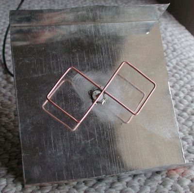
Before you buy a Wi-Fi antenna, think: theory shows that emitters located in rows narrow the radiation pattern in a direction perpendicular to the line along which the elements are lined up. Translated into Russian it means: if our houses and a friend’s are separated by 100 meters, the width of the antenna’s viewing sector for implementing a Wi-Fi communication channel barely exceeds 15 degrees. The useful power will be directed to the friend's window (it will only cause harm to the inhabitants of the apartment!). To implement the circuit, use a dual biquad antenna. You can increase the speed if you give the same one to a friend as a gift!
How to make a Wi-Fi antenna so that it doesn’t interfere with your neighbors. You can protect yourself from uninvited guests by changing the channel and polarization. Three methods have been found to protect the channel by antenna configuration:
- Frequency selection.
- Choice of direction (narrowing of the radiation pattern).
- Choice of polarization.

Usually, when there is Wi-Fi provided by the provider, the values are set by the communication provider, the client has to obey, but if he has his own equipment, the situation is different. We can install the antenna on vertical polarization if our neighbors use horizontal polarization. Our equipment will no longer see each other. This can be done unilaterally or by agreement. You will need antennas like biquad antennas, leave the supplied ones aside.
Television operates on horizontal polarization, and communications operate on vertical polarization. It’s just a tradition, it’s convenient to hold the radio pin perpendicular to the ground when you talk. In this context, it is advantageous to use vertical polarization, which is usually found in routers. We offer a simple rule:
- Position the antenna opposite the windows with a friend in the same way. Spatial compatibility is ensured, which is a subtype of electromagnetic compatibility. Microwaves, telephones, and a mountain of 2.4 GHz equipment were released, causing interference. Position the antennas equally, vertically, horizontally, tilted. Experimentally look for the position at which the speed is greatest.
The promised new product: a design of four squares lined up in a row. The radiation pattern will become narrow in the direction perpendicular to the formation. Copper wire or single-core wire with a cross-section of 2.5 mm 2 and a length of 50 cm. We recommend taking it with a reserve. If a standard biquad Wi-Fi antenna for a laptop is an in-phase array of two frames, in our case there are four frames.
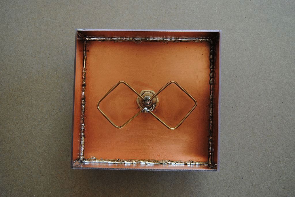
Frame for dual biquad antenna
When the wave moves, the current in neighboring squares is directed oppositely along the contour. Due to this, the effect of the field is added up. Now we need to get four in-phase squares. Find the middle of the wire and make a 90 degree bend. We measure 30 mm, make bends on each side in the opposite direction. We retreat twice as much, again pressing in the first direction. You will get a large letter W. Another 30 mm - bend the edges downwards at 90 degrees. One half is ready.
We make the second one in the same way so that the ends return to the point of the initial bend. Please note that it is not in vain that we recommend using a wire with a polyvinyl chloride sheath - the two crosshairs in the figure are mutually isolated.
We cut off the excess wire so that the ends do not reach two to three millimeters before the first bend. A Wi-Fi antenna for a computer requires a reflector; a good piece of foil PCB or standard flat sheet metal will do. We use an N-connector for connection.
The emitter is separated from the reflector by 1.5 cm in area. We place the ends on the ground, the middle - on the signal core (cable for Wi-Fi antenna RK - 50). To strengthen the edges of the figure, use ceramic or plastic tube. For fixation and electrical insulation, use glue or sealant. For the outdoor version, it is recommended to find a plastic case. Keep the distance between the homemade antenna and the receiver smaller.
The next meeting will discuss the Wi-Fi radio.
Digital signals have been known to everyone for a long time. All television organizations have switched to the new format. Analogue television devices have moved aside. But despite this, quite a few are in working condition and can last for more than one year. In order for outdated equipment to complete its allotted operational life, while still being able to view digital broadcasting, you will need to connect DVB-T to the TV receiver and catch wave signals with a zigzag antenna.
For those who want to save their family budget and at the same time receive high-quality television broadcasting, you need to pay attention to the Kharchenko antenna for digital TV with your own hands.
This unique design has been known for a long time, but found itself relatively recently.
Operating principle of an antenna for digital television
After radio communications appeared, the relevance of using an antenna device increased. Since the 60s of the twentieth century, the then recognizable engineer Kharchenko flaunted a design of 2 rhombuses. This device allowed him to catch US airwaves.
This is a double square made of thick copper wire. The squares are connected through open corners; this is where the cable from the TV is connected. To increase directivity, a grid made of material capable of conducting current is mounted at the rear.
The perimeter of the squares is equal to the wavelength to which the reception is tuned. The diameter of the wire should be about 12 mm for broadcasting from 1 to 5 TV channels. The design turns out to be far from compact, in the case of assembly for radio communications and meter-wave TV with up to 12 channels.

To make the device lighter, 3 wires of a smaller cross-section were used. Despite this, the size and weight remained impressive.
The antenna in question received its second wind when broadcasting appeared in the UHF range. Most people know rhombuses, triangles and other homemade figures in the form of antenna devices for receiving a signal of decimeter waves. Antennas of this type can be found on balconies and windows of both private houses and multi-storey buildings.
At the beginning of the 2000s, American professor Trevor Marshall came up with a proposal to use this design in Bluetooth and Wi-Fi networks.
The biquad antenna is also an antenna device of a Soviet engineer. This option is created according to the same principles as a regular biquadrat. A distinctive feature is that at the tops of the squares, instead of the corners, there are additional squares.

As for the sizes of these squares, they are identical to the usual ones. This avoids additional calculations. It is enough to use the standard biquadrat calculation.
Let us remind you that the wires in the place where they intersect require insulation from each other.
Required materials and tools
Kharchenko's DIY television antenna for DVB T2 is quite economical. In order to assemble the structure, you will need the following parts:
- Wire;
- Coaxial cable;
- Wooden slats.
As for tools: pliers, hammer, sharp knife. If you plan to attach the antenna device to a wall or other surface, you will most likely need a drill for mounting.

Antenna calculation
Before you start creating the design, you will need to calculate the Kharchenko antenna. This will allow you to assemble an effective device with maximum accuracy. Zigzag sizes DVB antennas T2 play a significant role in increasing signal reception.
Since technology has stepped forward, there is now no need to leaf through reference books or look for formulas for calculating dimensions. And even more so, carry out complex mathematical calculations in order to correctly develop a sketch or future drawing.
After this, you receive information: about the required length of the copper wire, its sides, and diameter.
Assembly of Kharchenko antenna for digital TV
Step-by-step instructions that will allow you to quickly assemble a Kharchenko antenna for digital television with your own hands:
- Determine the polarization and frequency of the wave. The device must be linear.
- The biquad type zigzag antenna device is made of copper. All elements are located at the corners, with one of them touching. For horizontal type polarization, the figure eight must stand upright. If you do vertical polarization, the structure lies on its side.

- The side of the square is calculated using a special formula - wavelength, which is divided by four.
- Imagine the structure, it should be oval in shape, and pulled together in the center across the larger side. The sides do not touch, but are in close proximity to each other.
- We connect the antenna cable to the approach points on both sides. It will be necessary to block one direction of the diagram; for this, a fetal screen made of copper is mounted; it will be located at a distance of 0.175 from the working wavelength. It should be placed on the cable braid.

As for the reflector, previously it was made of textolite boards that were coated with copper. Today, this component is made from metal plates. It is on this principle that the design for receiving digital television is made. Nothing complicated. Everything you need is at hand.
Antenna testing
The device has been created, it’s time to check the effectiveness of the work done. To test the reception quality of the wave channel, you need to connect the antenna to the receiver. Turn on the TV and receiver.
Open the main menu of the set-top box, select automatic channel search. On average, this process will only take a few minutes. You can find channels manually, but to do this you will have to enter their frequency. To test Kharchenko’s design for a TV, it’s enough to simply evaluate the quality of the broadcast. If the channels show well, then the job was done correctly.

What to do if interference is visible? Rotate the TV antenna and see if the picture quality improves. Once the optimal location is determined, simply secure the device. Naturally, it should be directed towards the TV tower.
Note.


